Making Two Raspberry Pi Pico Boards Communicate through SPI using C/C++ SDK
Tutorial on how to make two Raspberry Pi Pico boards communicate with each other through the SPI interface using Central/Peripheral modes and Pico C/C++ SDK.
The SPI (Serial Peripheral Interface) is one of the fastest communication interfaces you can find on a typical microcontroller. It is faster than UART, I2C, CAN, etc. So when you have so much data to transfer, such as from SD card, LCD, or a camera, you will need to use the SPI. In most cases, you will use a microcontroller as an SPI host (Central device) and all other devices as Peripherals. The central device will be in control of the writing and reading of all data. But sometimes you also want to make two microcontrollers communicate with each other through SPI for sending large amounts of data without errors. In this tutorial we are going to show you how you can make two Raspberry Pi Pico boards send and receive data through SPI, utilizing the Central and Peripheral working modes of SPI. This tutorial will also serve as the basis for using the SPI of the RP2040 microcontroller. We will use the official C/C++ SDK for compiling the code and VS Code as the IDE. If you are new to Raspberry Pi Pico and RP2040 microcontroller, we have a getting started tutorial for you.
Getting Started with Raspberry Pi Pico : RP2040 Microcontroller Board – Pinout, Schematic and Programming Tutorial
We can develop embedded firmware for you
CIRCUITSTATE can develop embedded firmware for any microcontroller/microprocessor including 8051, PIC, AVR, ARM, STM32, ESP32, and RISC-V using industry-leading SDKs, frameworks, and tools. Contact us today to share your requirements.
What is SPI?
Let’s give a brief introduction to the SPI first. SPI is a synchronous, full-duplex serial communication bus with three or more signals. It is synchronous because of the presence of a dedicated clock line shared between all nodes. The clock helps all devices taking part in the communication to remain in sync. This increases the effective data rate on the line while reducing errors. Full-duplex means data can be sent and received at the same time using the dedicated data lines. In a standard application, there will be four signal lines.
- COPI – This stands for Controller Out Peripheral In or Master Out Slave In (MOSI) in obsolete terms. This pin is the data output pin for the Central device but also at the same time, the data input pin for the Peripheral device.
- CIPO – This stands for Controller In Peripheral Out or Master In Slave Out (MISO) in obsolete terms. This pin is the data output of the Peripheral node and thus the data input pin for the Central node.
- SCK – This is the common Serial Clock line shared between all devices. Only the Central node can generate the clock. All other devices must read the clock.
- CS – Chip Select is the line used to select a device on the bus. Each node needs a separate CS line for selecting that device. The state of the CS line will be
HIGHby default when the device is not selected. To select the device, a Central node must pull the CS line of that device toLOW.
Only one device can generate a clock signal on the SCK line at a time. This device with the role of generating the SPI clock is called a Central node, also called Master in obsolete terms. All other devices will act like Peripheral (or Slave) nodes at this time. There needs to be at least one Central node and one Peripheral node to make SPI work. Two Peripheral nodes connected to each other will not work since no devices can generate the clock. The COPI, CIPO, and SCK lines are common to all devices (central and peripheral nodes). When the Central node wants to send/receive some data, it can generate a clock of specific frequency on the SCK line and assert the data on the COPI line. But before doing that, the Central node must indicate which device should receive this data. It is done by pulling the CS line of the corresponding Peripheral device to LOW, while pulling all other CS pins to HIGH.
Since only the Central node can generate the clock, only a central node can initiate a data transfer. Therefore, SPI communication must employ a Command-Response scheme for communication. A Central node can pull the CS pin of a node LOW and then send some command to it. Upon receiving the command, the Peripheral node starts sending the response data. The Central must maintain the clock signal for the period of time the peripheral is sending data. You can learn more about SPI interface from the tutorial below.
RP2040 SPI
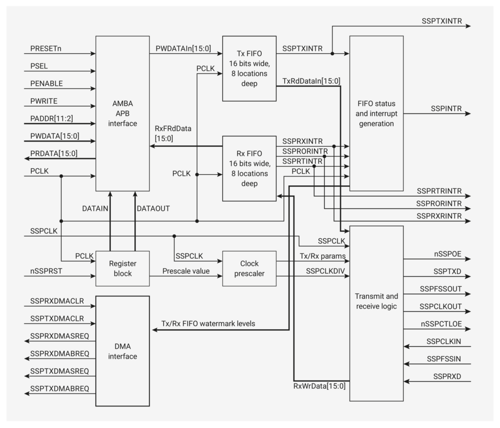
RP2040, the microcontroller found on the Raspberry Pi Pico board has two identical SPI controllers inside. The SPI controllers are based on the PrimeCell Synchronous Serial Port (SSP) from ARM. Each SPI controller comes with the following features.
- Master or Slave modes
- Motorola SPI-compatible interface
- Texas Instruments synchronous serial interface
- National Semiconductor Microwire interface
- 8 deep Tx and Rx FIFOs
- Interrupt generation to service FIFOs or indicate error conditions
- Can be driven from DMA
- Programmable clock rate
- Programmable data size 4-16 bits
Both RX and TX FIFOs (First In First Out, a buffer memory for storing data) are 16-bit wide, allowing us to write 16-bit data directly. The FIFOs are 8 locations deep, which means a total of 32 bytes. The pins for both of the SPI controllers can be assigned to multiple GPIO pins using the GPIO Mux block of RP2040. Each SPI block can have a maximum of 8 signal lines as described below.
| Name | Direction | Description |
|---|---|---|
| SSPFSSOUT | Output | Equivalent to CS output from the Central node |
| SSPCLKOUT | Output | Clock output (SCK) from the Central node |
| SSPRXD | Input | Data receive line (CIPO) for Central |
| SSPTXD | Output | Data output line (COPI) for Central |
| nSSPCTLOE | Output | Controls the SSPCLKOUT signal. Active-LOW. 1 = Peripheral mode, 0 = Central mode. |
| SSPFSSIN | Input | Equivalent to CS input for Peripheral mode |
| SSPCLKIN | Input | Clock input for Peripheral mode |
| nSSPOE | Output | Controls the SSPTXD line. Active-LOW. 1 = TX output is disabled, 0 = TX output is enabled. |
That’s more than four signals we talked about earlier. But don’t worry. Depending on the role of the SPI interface (Central or Peripheral), those signals will be routed to their appropriate pins. The Pico C/C++ SDK has APIs (Application Programming Interface) to control and configure the SPI controllers as we will see later. One thing you must keep in mind is that the SPI controller of RP2040 can not switch between Central and Peripheral roles dynamically. The user has to deinit the mode and reinitialize the SPI in a different mode manually. The RP2040 datasheet has a detailed explanation of its SPI controller and associated registers. You can also learn about PrimeCell from ARM documentation.
Wiring
We are going to use two Raspberry Pi Pico boards for this tutorial. We will use one Pico as the Central node and the other as the Peripheral node. We will use the SPI0 instance of the RP2040 and their default GPIO pins. Connect the two boards as shown below.
| Central | Peripheral |
|---|---|
| CS (GPIO 17) | CS (GPIO 17) |
| SCK (GPIO 18) | SCK (GPIO 18) |
| COPI (GPIO 19) | CIPO (GPIO 16) |
| CIPO (GPIO 16) | COPI (GPIO 19) |
| GND | GND |
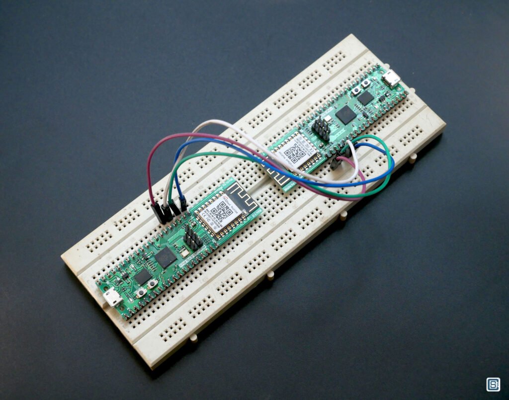
Notice how the COPI of the Central is connected to CIPO of the Peripheral. This might seem wrong at first look because we always connect the CIPO of a Central device to the CIPO of a Peripheral device when interfacing a sensor or display, for example. That is only because such sensors or devices are designed to be operated as Peripheral devices at all times. Therefore their TX/RX pins always have fixed functions. But since RP2040 can change its roles, the behavior of the pins will also change. The default pin assignments for the SPI0 controller (Central mode) are as below. You can remap these functions to other compatible GPIO pins.
| GPIO # | Pin Name | SPI Function |
|---|---|---|
| 17 | SPI0 CSn | CS |
| 18 | SPI0 SCK | SCK |
| 19 | SPI0 TX | COPI |
| 16 | SPI0 RX | CIPO |
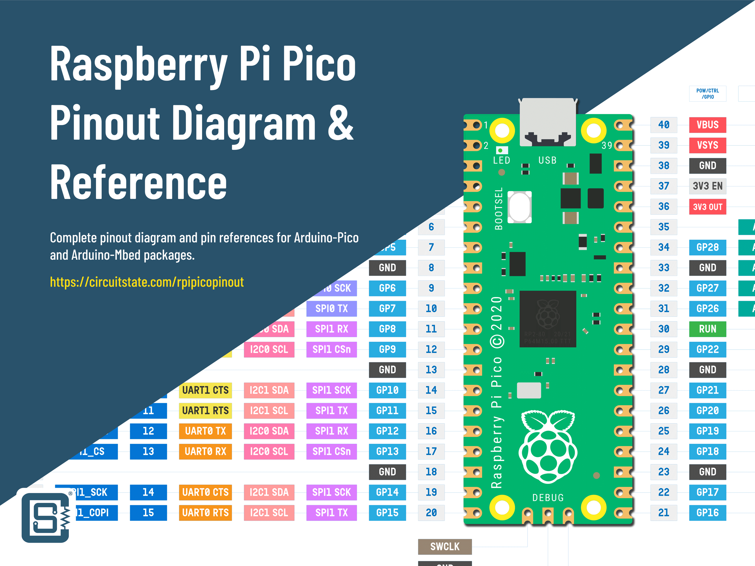
We have a complete pinout diagram for the Raspberry Pi Pico board and RP2040 which you can find below. We are using the WizFi360-EVB-Pico boards from WizNet here because they have dedicated RESET and BOOTSEL buttons which avoids the need for disconnecting and reconnecting the USB cable every time to program the board! Otherwise, WizFi360-EVB-Pico and the official Raspberry Pi Pico are functionally identical.
Raspberry Pi Pico RP2040 Microcontroller Board – Pinout Diagram & Arduino Pin Reference
Central-Peripheral Communication
We are going to use the official Pico C/C++ SDK for RP2040 for compiling the code. You will need to set up a build environment for the Pico SDK in order to compile the example codes. The examples below are modified versions of the official SPI examples.
Central Node
This is the code for the Pico board with the Central role. This example is a modified version of the official spi_slave example.
//=================================================================================//

#include <stdio.h>
#include "hardware/spi.h"
#include "pico/binary_info.h"
#include "pico/stdlib.h"

//=================================================================================//

#define BUF_LEN 128

//=================================================================================//

int main() {
  // Enable USB serial so we can print
  stdio_init_all();

  sleep_ms (2 * 1000);
  printf ("SPI Central Example\n");

  // Enable SPI0 at 1 MHz
  spi_init (spi_default, 1 * 1000000);

  // Assign SPI functions to the default SPI pins
  gpio_set_function (PICO_DEFAULT_SPI_RX_PIN, GPIO_FUNC_SPI);
  gpio_set_function (PICO_DEFAULT_SPI_SCK_PIN, GPIO_FUNC_SPI);
  gpio_set_function (PICO_DEFAULT_SPI_TX_PIN, GPIO_FUNC_SPI);
  gpio_set_function (PICO_DEFAULT_SPI_CSN_PIN, GPIO_FUNC_SPI);

  // We need two buffers, one for the data to send, and one for the data to receive.
  uint8_t out_buf [BUF_LEN], in_buf [BUF_LEN];

  // Initialize the buffers to 0.
  for (u_int8_t i = 0; i < BUF_LEN; ++i) {
    out_buf [i] = 0;
    in_buf [i] = 0;
  }

  for (uint8_t i = 0; ; ++i) {
    printf ("Sending data %d to SPI Peripheral\n", i);
    out_buf [0] = i;
    // Write the output buffer to COPI, and at the same time read from CIPO to the input buffer.
    spi_write_read_blocking (spi_default, out_buf, in_buf, 1);

    // Sleep for some seconds so you get a chance to read the output.
    sleep_ms (2 * 1000);
  }
}

//=================================================================================//
BUF_LEN is the length in bytes for the input and output buffers we are going to use with SPI. In the main() function, we start with initializing the standard input and outputs using stdio_init_all() so that we can print debug information using printf() function. As to which interface should be used for standard input and output must be defined in the CMake configuration file CMakeLists.txt. The official example files are missing this configuration. So we had to add them.
The next line will enable and initialize the SPI port. The SPI instance we are using is the default one spi_default which is actually spi0. The second parameter is the SPI clock frequency in Hz. We are using 1 MHz here. That is almost equivalent to 1 Mbps (the actual data rate will lower because of SPI framing overhead). The maximum SPI data rate of RP2040 is around 62.5 Mbps (62.5 MHz). Sending any frequency value does not guarantee that the value will be set exactly. Instead, the closest possible value will be set. Initializing the SPI instance will set it to Central mode by default.
spi_init (spi_default, 1 * 1000000);Next, we need to assign functions to the GPIO pins we want to use. In this example, the default pins for the default SPI are already defined as macros. We just need to initialize the GPIO pins with their respective functions. Even though peripheral functions can be assigned to multiple GPIO pins, there are no overlaps for the same peripheral functions. That means if you set, for example, pin PICO_DEFAULT_SPI_RX_PIN to an SPI peripheral, the function will always be RX pin.
  // Assign SPI functions to the default SPI pins
  gpio_set_function (PICO_DEFAULT_SPI_RX_PIN, GPIO_FUNC_SPI);
  gpio_set_function (PICO_DEFAULT_SPI_SCK_PIN, GPIO_FUNC_SPI);
  gpio_set_function (PICO_DEFAULT_SPI_TX_PIN, GPIO_FUNC_SPI);
gpio_set_function (PICO_DEFAULT_SPI_CSN_PIN, GPIO_FUNC_SPI);Next, we create two new buffers called out_buf and in_buf. These will hold the bytes of data we will send and receive through SPI. We can initialize both buffers to 0 but it’s not necessary. Next comes a for loop that will repeat indefinitely. Each time it also increments the iterator i from 0 to 127 which we will use as the output data. spi_write_read_blocking() is one of the API functions available for the SPI. The first parameter to the function is the SPI instance, the second parameter is the output buffer, the third parameter is the input buffer and the last parameter is the number of bytes we want to read or write. When the function is called, the specified number of bytes are read or written at the same time. Both write and read operations can be executed simultaneously because the SPI is a full-duplex interface. In this case, we are only writing a single byte.
spi_write_read_blocking (spi_default, out_buf, in_buf, 1);All SPI read and write functions are blocking in nature. For example, if you specify reading of 10 bytes from SPI, then the function will wait for an indefinite time until it completely read 10 bytes. That will block all other parts of the code from being executed. So you should make sure to read only the number of bytes you need. Finally, we wait for 2 seconds using sleep_ms() call before sending the next byte. This is so that the Peripheral will have time for reading the data. Sending data faster than the Peripheral can read or process will cause the SPI FIFOs to overflow and lose data.
Peripheral Node
The code for the Peripheral node is given below. The only main difference between the Central code is the presence of the call to the function spi_set_slave(). This will set the SPI interface to Peripheral mode.
//=================================================================================//

#include <stdio.h>
#include "hardware/spi.h"
#include "pico/binary_info.h"
#include "pico/stdlib.h"

//=================================================================================//

#define BUF_LEN 128

//=================================================================================//

int main() {
  // Enable UART so we can print
  stdio_init_all();
  sleep_ms (2 * 1000);
  printf ("SPI Peripheral Example\n");

  // Enable SPI 0 at 1 MHz and connect to GPIOs
  spi_init (spi_default, 1 * 1000000);
  spi_set_slave (spi_default, true);

  gpio_set_function (PICO_DEFAULT_SPI_RX_PIN, GPIO_FUNC_SPI);
  gpio_set_function (PICO_DEFAULT_SPI_SCK_PIN, GPIO_FUNC_SPI);
  gpio_set_function (PICO_DEFAULT_SPI_TX_PIN, GPIO_FUNC_SPI);
  gpio_set_function (PICO_DEFAULT_SPI_CSN_PIN, GPIO_FUNC_SPI);

  uint8_t out_buf [BUF_LEN], in_buf [BUF_LEN];

  // Initialize output buffer
  for (uint8_t i = 0; i < BUF_LEN; ++i) {
    out_buf [i] = 0;
    in_buf [i] = 0;
  }

  while (1) {
    if (spi_is_readable (spi_default)) {
      printf ("Reading data from SPI..\n");
      // Write the output buffer to MOSI, and at the same time read from MISO.
      spi_read_blocking (spi_default, 0, in_buf, 1);

      printf ("Data received: %d\n", in_buf [0]);
    }
  }
}

//=================================================================================//
In the main() function, we have a while loop that polls for new data on the SPI. If new data comes to the SPI port, it will be temporarily saved to the receive FIFO until the user reads it. The function spi_is_readable() will check if there is data on the FIFO and returns true if there is. We repeatedly call this function and when it returns true, we will read the data from the SPI using spi_read_blocking() call. We have to specify the SPI instance, the data to send during the read operation (it can be 0 in our case), the input buffer and the number of bytes to read.
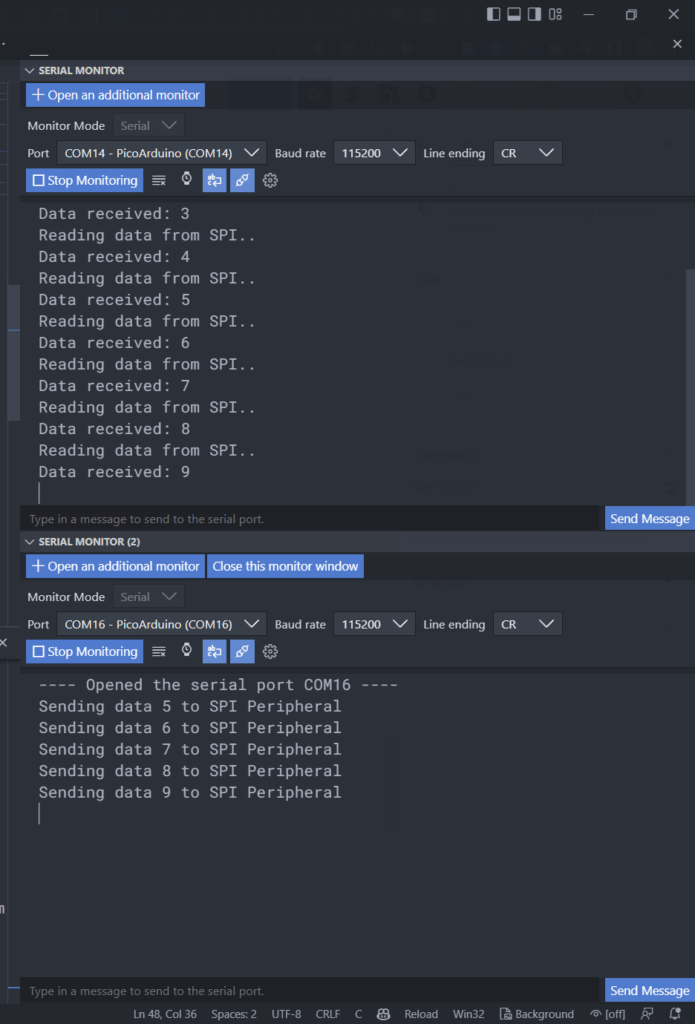
You can compile and upload the code to two Pico boards and open two serial monitors simultaneously to see that the Central is sending the data and at the same time, the Peripheral is receiving the data and printing it. Below is a screenshot from VS Code IDE.
Working with the other SPI (spi1) is similar in every way. You just need to replace the SPI instances and pin assignments. More details on the C/C++ APIs for the SPI can be found in the official Pico SDK documentation. One limitation of the official APIs is that they don’t support interrupts for SPI. If you need more SPI ports and faster data rates, you can use the PIO (Programmable IO) block of RP2040.
SPI Receive Interrupt
In the previous example, we used the polling method to see if any new data has been received on the Peripheral side. But the RP2040 SPI also supports generating interrupts on certain events. But unfortunately, the official SDK doesn’t implement any of those and there are no examples given. So let’s see how we can implement an ISR (Interrupt Service Routine) to read incoming SPI data using interrupts. We have to make a few modifications to the Peripheral code as shown below. The code for the Central node can be the same as before.
//=================================================================================//

#include <stdio.h>
#include "hardware/spi.h"
#include "pico/binary_info.h"
#include "pico/stdlib.h"

//=================================================================================//

#define BUF_LEN     128
#define SPI_RW_LEN  1

uint8_t out_buf [BUF_LEN], in_buf [BUF_LEN];

//=================================================================================//

void spiReceiveISR() {
  printf ("Reading data from SPI with interrupt..\n");
  spi_read_blocking (spi_default, 0, in_buf, SPI_RW_LEN);
  printf ("Data received: %d\n", in_buf [0]);
}

//=================================================================================//

int main() {
  // Enable UART so we can print
  stdio_init_all();
  sleep_ms (2 * 1000);
  printf ("SPI Peripheral Example\n");

  const uint LED_PIN = PICO_DEFAULT_LED_PIN;
  gpio_init (LED_PIN);
  gpio_set_dir (LED_PIN, GPIO_OUT);

  // Enable SPI 0 at 1 MHz and connect to GPIOs
  spi_init (spi_default, 1 * 1000000);
  spi_set_slave (spi_default, true);

  gpio_set_function (PICO_DEFAULT_SPI_RX_PIN, GPIO_FUNC_SPI);
  gpio_set_function (PICO_DEFAULT_SPI_SCK_PIN, GPIO_FUNC_SPI);
  gpio_set_function (PICO_DEFAULT_SPI_TX_PIN, GPIO_FUNC_SPI);
  gpio_set_function (PICO_DEFAULT_SPI_CSN_PIN, GPIO_FUNC_SPI);

  // Enable the RX FIFO interrupt (RXIM)
  spi0_hw->imsc = 1 << 2;

  // Enable the SPI interrupt
  irq_set_enabled (SPI0_IRQ,1);

  // Attach the interrupt handler
  irq_set_exclusive_handler (SPI0_IRQ, spiReceiveISR);

  while (1) {
    gpio_put (LED_PIN, 1);
    sleep_ms (250);
    gpio_put (LED_PIN, 0);
    sleep_ms (250);
    gpio_put (LED_PIN, 1);
    sleep_ms (250);
    gpio_put (LED_PIN, 0);
    sleep_ms (1000);
  }
}

//=================================================================================//
We have added a new macro SPI_RW_LEN to set the read-write length for the SPI just for convenience. We have also made the buffers global variables, so that we can access them from any function. spiReceiveISR() is our ISR for reading the incoming SPI data. The function simply reads the data from the FIFO and prints it. In order to enable the interrupt, we first need to set the RXIM (Receive FIFO interrupt mask) interrupt mask on the SSPIMSC register of the RP2040. This is done as shown below.
// Enable the RX FIFO interrupt (RXIM)
spi0_hw->imsc = 1 << 2;That will generate an interrupt whenever the receive FIFO is half full. Now in order to attach an ISR for the interrupt, we need to use the SPI0_IRQ (for spi0) interrupt request channel. It is one of the 26 interrupt sources available for RP2040. SPI0_IRQ is a common interrupt source that will be invoked for all related interrupts for SPI0. If you are using SPI1 then you must use SPI1_IRQ as the interrupt source. Enabling the interrupt source can be done by calling the irq_set_enabled() call.
// Enable the SPI interrupt
irq_set_enabled (SPI0_IRQ,1);Finally, the ISR can be attached using the irq_set_exclusive_handler() function call. The first parameter is the interrupt source and the second parameter is the ISR. The ISR should be of void type.
// Attach the interrupt handler
irq_set_exclusive_handler (SPI0_IRQ, spiReceiveISR);In order to show that the interrupt is working, we have also added a while loop to blink the LED and two lines of code to initialize the LED GPIO pin. When you run the program, you can see that the LED is blinking and if you open the serial monitor, you can see the spiReceiveISR() is printing the data. The LED blinking loop will be interrupted for a very short time but you will never notice it.
Multiple SPI Peripherals
In the previous examples, we only had a single Peripheral on the SPI bus. But what if we have multiple Peripherals? In the last example, the CS pin of the Peripheral was driven by the Central hardware automatically. This is because we had initialized the CS pin with SPI function with the following line in the Central’s code.
gpio_set_function (PICO_DEFAULT_SPI_CSN_PIN, GPIO_FUNC_SPI);If we want to control the CS pin in the software, we have to first remove the above line from the code and then initialize the CS pis as a GPIO output pin as shown below.
gpio_init (PICO_DEFAULT_SPI_CSN_PIN);
gpio_set_dir (PICO_DEFAULT_SPI_CSN_PIN, GPIO_OUT);We can then pull the CS pin LOW before calling any SPI read/write functions. Similarly, we can assign separate GPIOs for CS functionality of each Peripheral we have on the bus. After that, the Central node can select the Peripheral device it wants to communicate with, by pulling the CS pin LOW while pulling all other pins HIGH.
gpio_put (PICO_DEFAULT_SPI_CSN_PIN, 0); // Select the Peripheral deviceSPI Settings
The C/C++ SDK gives APIs to configure the SPI port. For example, the spi_set_baudrate() call sets the actual baud rate (data rate) you need in Hz. The closest possible value will be set and returned. The spi_set_format() allows setting the number of bits in a frame, clock polarities, and data endianness.
Compiling with VS Code
If you already know how to create standalone Pico SDK projects and compile them, then you can simply copy-paste the code from the previous sections. But if you want to know how to create standalone Pico projects, we have a dedicated tutorial for it.
How to Create A Standalone Raspberry Pi Pico C/C++ Project in Windows and Build from Command-Line and VS Code
After compiling the source files, your build directory will have different types of binary files. You can use the UF2 file if you want to upload the code via USB Mass Storage mode. You just need to press the RESET button of Pico while holding the BOOTSEL button. If you don’t have a RESET button, in the case of the official Pico board, you can power up the board by holding the BOOTSEL button. This will put the Pico in USB Mass Storage mode. To help you easily test the code, we have provided a download link to the entire project.
Links
- RP2040 Datasheet [PDF]
- Raspberry Pi Pico Datasheet [PDF]
- Getting started with Raspberry Pi Pico [PDF]
- Raspberry Pi Pico C/C++ SDK [PDF]
- Raspberry Pi Pico C/C++ SDK Documentation
- PrimeCell Synchronous Serial Port (SSP)
- Getting Started with WizFi360-EVB-Pico – RP2040 and Wi-Fi Development Board from WIZnet
- How to Create A Standalone Raspberry Pi Pico C/C++ Project in Windows and Build from Command-Line and VS Code
- Getting Started with Raspberry Pi Pico : RP2040 Microcontroller Board – Pinout, Schematic and Programming Tutorial
- Raspberry Pi Pico Microcontroller Board – Pinout Diagram & Reference
Short Link
- Short URL to this page – https://circuitstate.com/picospicenper




This is an excellent tutorial. I was looking to use I2C, until I found this! And the code works, too!
Question 1: Can I daisy chain multiple peripheral Picos?
Question 2: How would I address each individual extra Pico? Like, what would I have to change in the code?
Hi Lewis. Yes, you can connect multiple peripheral devices to a single host controller. You just need separate Chip Select (CS) pins for each peripheral. The remaining SPI pins can be common across these multiple peripherals. During communication, you need to pull the CS pin of the peripheral you want to communicate with, to LOW. Meanwhile, all of the other CS pins should be pulled-up to HIGH. This is how you select the peripheral to communicate with. To use custom GPIO pins for SPI, do not set the pin function to
GPIO_FUNC_SPIusinggpio_set_function(). Instead, set each CS pin as GPIO output and manually pull them LOW/HIGH just before SPI transfers. Please check the Multiple SPI Peripherals section for more info.