Interfacing Incremental Rotary Encoder with Arduino
Tutorial on interfacing incremental mechanical rotary encoder with Arduino. Interrupt based example code is included.
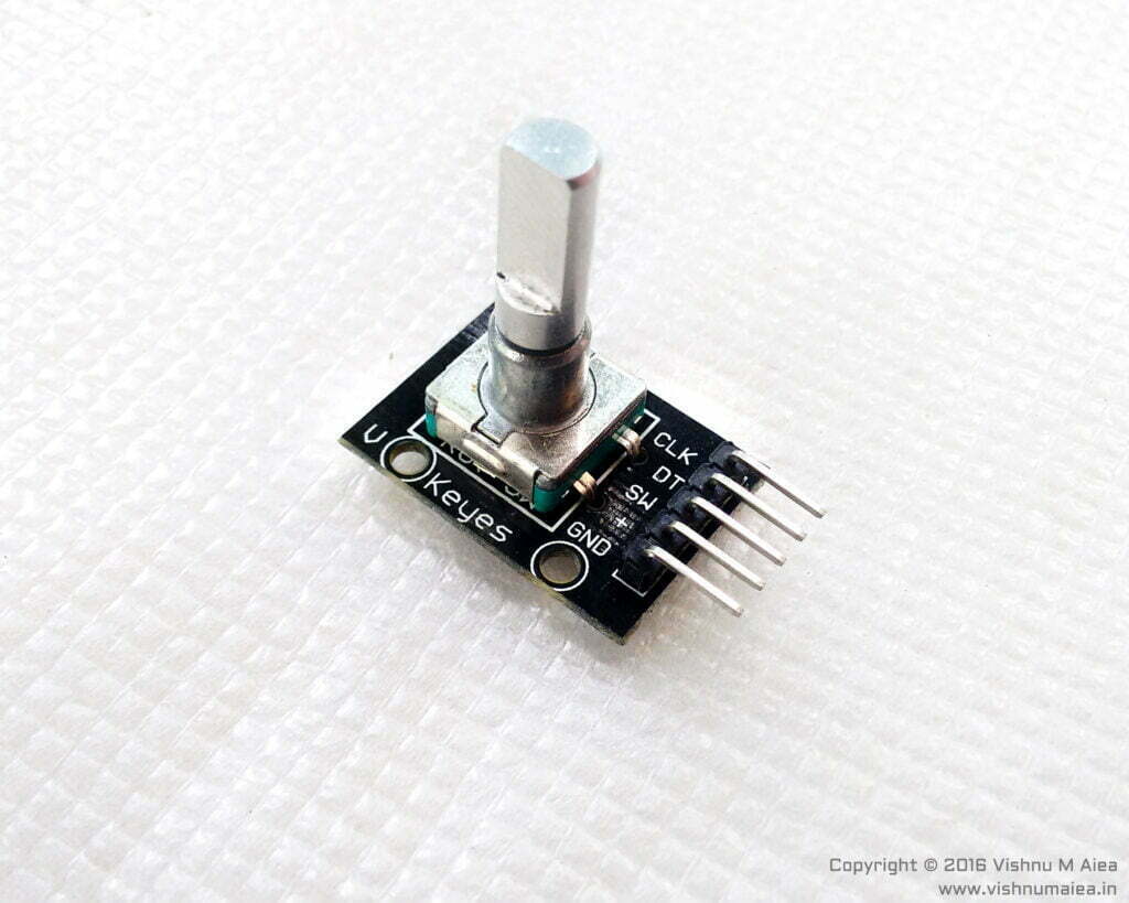
A rotary encoder is a cleverly designed piece of hardware that finds use in every project that requires sensing the rotatory motion of some shaft, knob, etc, to find the direction of rotation, angular velocity, etc. There are many types of rotary encoders of which some are designed for specific advanced applications. In this tutorial, we will be using one of the many types of rotary encoder called an incremental rotary encoder or quadrature encoder as it is sometimes called. It works by mechanical means.
If you want to know more about a rotary encoder and how it actually works, go to Dejan Nedelkovski‘s rotary encoder tutorial here. He has also published a well-explained video tutorial on rotary encoders which can be found here on YouTube. Continue from here after you’ve done that because I’m not going to talk about how it works in detail.
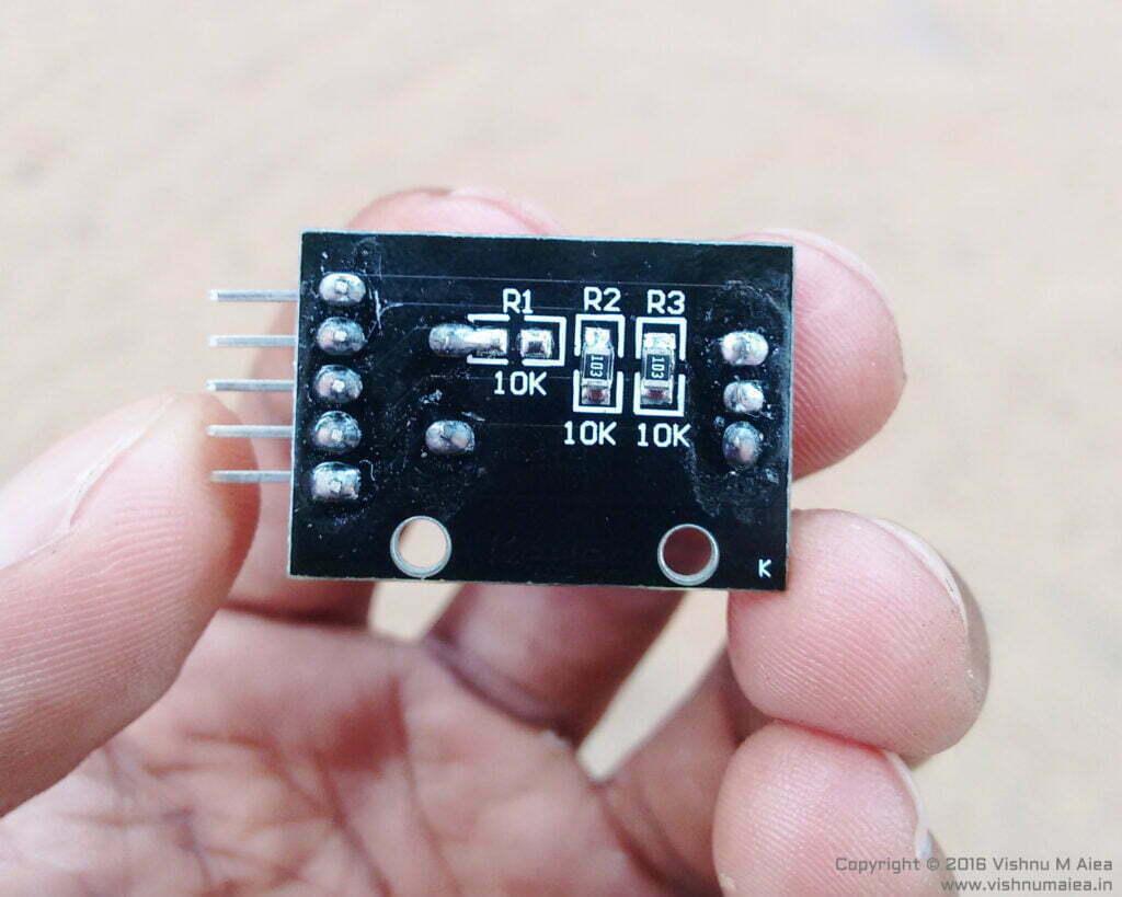
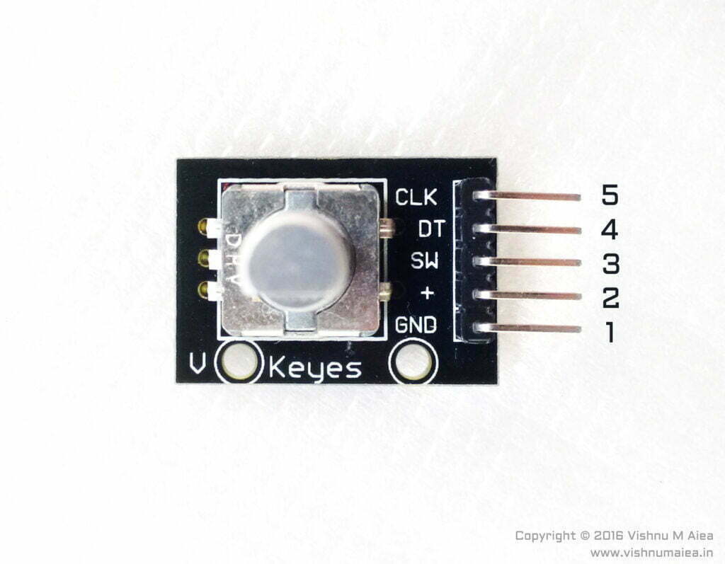
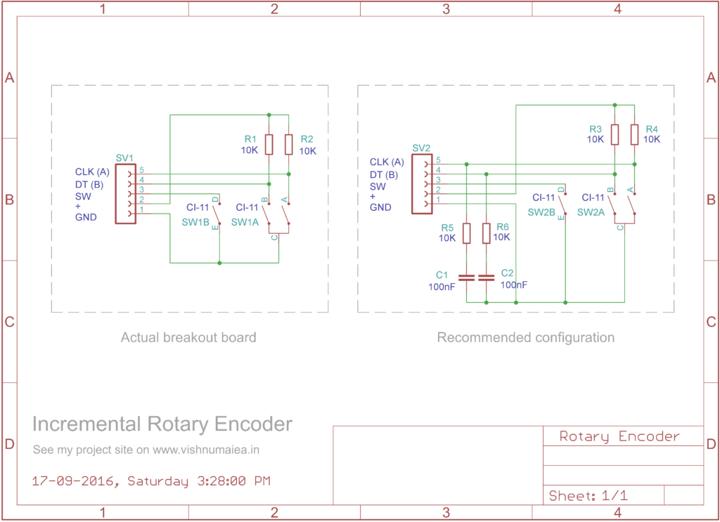
Following is the schematic of my breakout board. Two 10K pull-up resistors are connected to pins A (CLK) and B (DT) and tied to the +5V pin. The common pin of the encoder is connected to the GND pin of the board. The particular breakout board we have is missing a 10K pull-up for the center switch which is not necessary if you have it in your controller already. The center push-button is activated by pressing the actuator vertically. It could be used as a mode select switch. The output of the switch is available at pin SW. The encoder we have has 30 steps or resolution which yields 12° per step which is enough for most control inputs.
Simply connect the breakout board as per the schematic and pins A and B to digital Pin-6 and Pin-7 of the Arduino Uno board respectively. Then upload the code from Dejan Nedelkovski to the Arduino board to test your encoder.
/*     Arduino Rotary Encoder Tutorial
 *
 *  by Dejan Nedelkovski, www.HowToMechatronics.com
 *
 */

#define outputA 6
#define outputB 7
int counter = 0;
int aState;
int aLastState;

void setup() {
  pinMode(outputA, INPUT);
  pinMode(outputB, INPUT);

  Serial.begin(9600);
  // Reads the initial state of the outputA
  aLastState = digitalRead(outputA);
}

void loop() {
  aState = digitalRead(outputA); // Reads the "current" state of the outputA
  // If the previous and the current state of the outputA are different,
  //that means a Pulse has occured
  if (aState != aLastState) {
    // If the outputB state is different to the outputA state,
    //that means the encoder is rotating clockwise
    if (digitalRead(outputB) != aState) {
      counter++;
    }
    else {
      counter--;
    }
    Serial.print("Position: ");
    Serial.println(counter);
  }
  aLastState = aState; // Updates last state of outputA with current state
  delay(50);
}If everything is done correctly, when you open the serial monitor and rotate the encoder you will see the rotation count printed there.
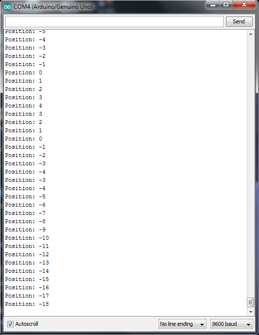
So far we are good. But there is a problem. The above code is just for demonstrating how the encoder works. But for practical applications, there is a problem that you have to tackle. Because the above-mentioned code uses “polling” to detect any change in the encoder position. That means the loop in the code just continuously checks the status of the encoder and updates the counter. But what if your code has to do more than that, and that adds a delay to it? With the polling method, you might miss some increments produced by the encoder. The solution is to use interrupts for reading the encoder. With interrupt-enabled code, you are guaranteed to read the encoder even with delays in your code. The interrupt routines will only be called when there is a change in the encoder position when you rotate it.
Kevin Darrah has an encoder video tutorial and interrupt-based interfacing code. But his code did not work for us for some reason. To write the code of our own, we can use the following logic waveform of an encoder.
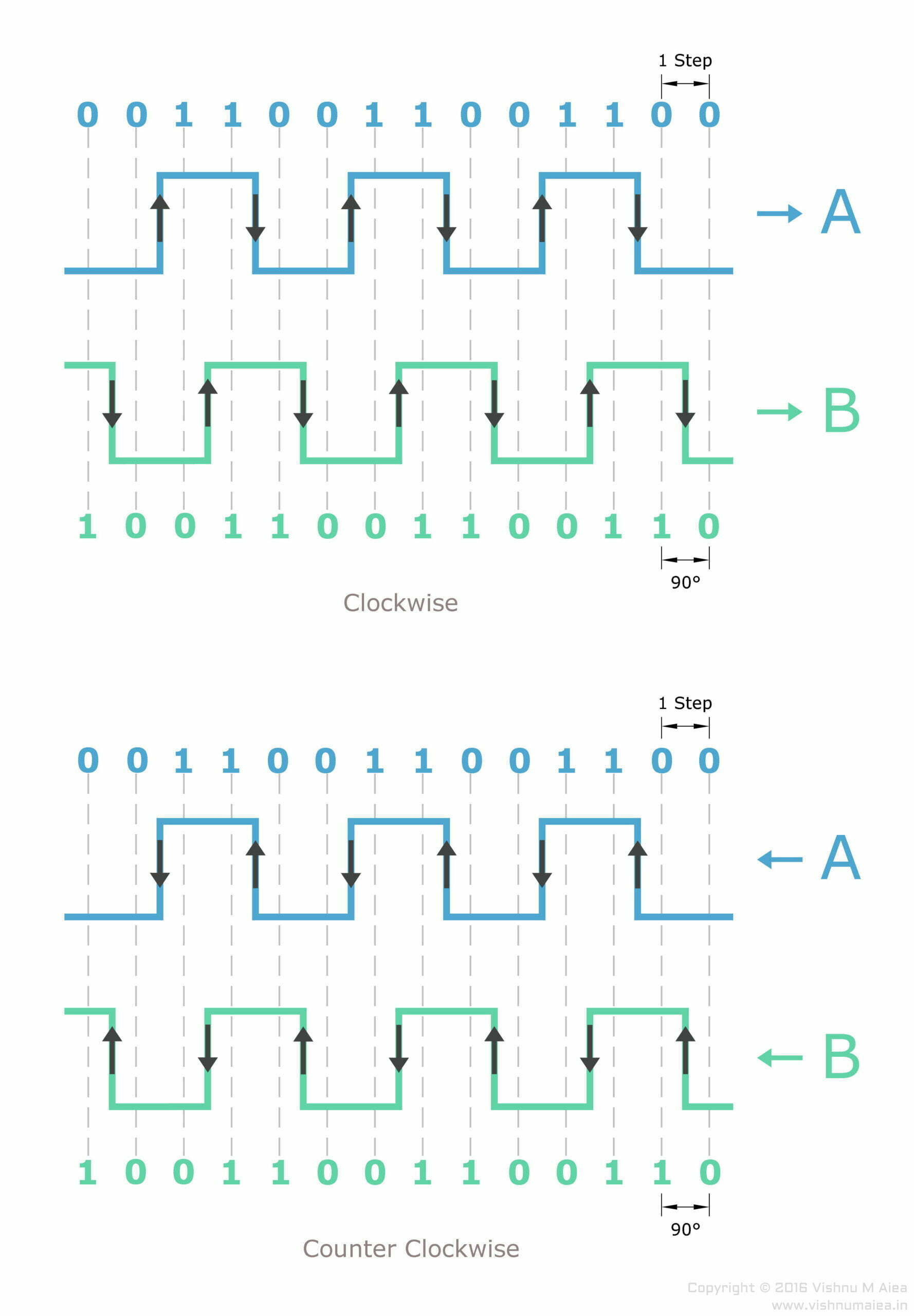
From the output waveform, it is obvious that pins A and B produce different output pairs for clockwise and counterclockwise rotations. We can use this to design an ISR (Interrupt Service Routine) to update a counter. We have to only use one pin to detect the rising edge and falling edge to run the ISR because the other pin’s state will not change at that time. Here we will use pin A (whatever physical pin that is) to detect the rising and falling edge and then run the ISR. When pin A changes its state by rising or falling, the state of B will be unchanged.
This code is written for Arduino Uno and uses its external interrupt capability. Digital pins 2 and 3 are the interrupt-enabled pins in Uno. So you need to connect your encoder accordingly. If you are using a different Arduino board, use an available external interrupt pin.
int pulseCount; // Rotation step count
int SIG_A = 0; // Pin A output
int SIG_B = 0; // Pin B output
int lastSIG_A = 0; // Last state of SIG_A
int lastSIG_B = 0; // Last state of SIG_B
int Pin_A = 2; // Interrupt pin (digital) for A (change your pins here)
int Pin_B = 3; // Interrupt pin (digital) for B

void setup() {
  SIG_B = digitalRead (Pin_B); // Current state of B
  SIG_A = SIG_B > 0 ? 0 : 1; // Let them be different
  // Attach iterrupt for state change, not rising or falling edges
  attachInterrupt (digitalPinToInterrupt (Pin_A), A_CHANGE, CHANGE);
  Serial.begin (9600);
}

void loop() {
  // Does nothing here. Add your code here.
}

void A_CHANGE() { // Interrupt Service Routine (ISR)
  detachInterrupt (0); // Important
  SIG_A = digitalRead (Pin_A); // Read state of A
  SIG_B = digitalRead (Pin_B); // Read state of B

  if ((SIG_B == SIG_A) && (lastSIG_B != SIG_B)) {
    pulseCount--; // Counter-clockwise rotation
    lastSIG_B = SIG_B;
    Serial.print (pulseCount);
    Serial.println (" - Reverse");
  }

  else if ((SIG_B != SIG_A) && (lastSIG_B == SIG_B)) {
    pulseCount++; // Clockwise rotation
    lastSIG_B = SIG_B > 0 ? 0 : 1; // Save last state of B
    Serial.print (pulseCount);
    Serial.println (" - Forward");
  }
  attachInterrupt (digitalPinToInterrupt (Pin_A), A_CHANGE, CHANGE);
}Unlike many other interfacing codes you might find on the web, this code does not “miss” steps and doesn’t add any delays to other parts of your code. It only uses a single pin to detect rising and falling edges to trigger the ISR and therefore the code and its logic are less complex and easy to understand.
When we rotate the encoder in a clockwise direction, the output of A changes twice; one rising edge and one falling edge. In the waveform diagram, the UP arrow indicates a rising edge or positive-going edge and the DOWN arrow indicates a falling edge or negative-going edge. At the rising edge of A or when it becomes 1 (HIGH), the state of B would be opposite to that, ie 0 (LOW). This is the same for the falling edge of A. So for clockwise rotation, A and B will always be in opposite states.
For counter-clockwise rotation, the rising edge and falling edges of A will be equal to the state of B. You can see that in the waveform diagram. So we can just check if SIG_A equals SIG_B whenever a state change occurs to output A.
But there is a small issue. Just checking if A equals B does not determine whether the encoder is rotated clockwise or counterclockwise for the first time. If you take a closer look at the waveform you will notice that the state change happens to A in the same part of the graph could be a rising or falling edge. As we are not detecting rising or falling edges of A directly but just detecting any state change, we can not be sure about whether we have detected a rising edge or falling edge. To determine that, we need to know the previous state of A or B. Here, we used B‘s current state and last state to determine the falling edge and the rising edge of A, because it would be easier to interpret it from the waveform. So that is what the following lines do.
if ((SIG_B == SIG_A) && (lastSIG_B != SIG_B))
else if ((SIG_B != SIG_A) && (lastSIG_B == SIG_B))In the first if block, we save the current state of B to lastSIG_B. But in the next else if block, we save the lastSIG_B as the inverse of the current state of B. This is because we are not detecting any change that happens to output B. Such change to B happens halfway around when we rotate the shaft for one step. So there is no way can detect it when it happens. But we could assume what would happen. Therefore, we save the inverse of SIG_B to lastSIG_B so that the next time we detect a clockwise operation, we will not miss a step. Otherwise, you will miss intermediate clockwise steps. Try disabling the line lastSIG_B = SIG_B > 0 ? 0 : 1; or replacing it with lastSIG_B = SIG_B; to see what happens.


Thanks for an informative post.
The diagram showing the recommended configuration for the encoder board has an error, I believe. The way it is laid out means that the RC filter has no effect. The external connections should be to the junctions of R5/C1 and R6/C2.
Thanks for your feedback, Ted. This tutorial was written a long time ago and is in need of an update. We will fix the issue in the next update.