How to Write Parallel Multitasking Applications for ESP32 using FreeRTOS & Arduino
ESP32 is a powerful and feature-rich SoC from Espressif. It is undoubtedly one of our favorites. Part of the reason why we like it so much is that it is a dual-core SoC with a fast operating clock and large memory capacity. Two cores mean there are two separate processors inside the SoC die. To fully take advantage of these awesome hardware features, the usual sequential programming method is not enough. Sequential programming or execution is when one task is executed while all other tasks wait for the running task to finish. In contrast, if you think about your personal computer, you know that you can do multiple tasks at a time as if each task/application is running parallel and independently of the other. While sequential programming can do that if run fast enough, there are real advantages to making use of “true parallelism” with multiple cores. Fortunately, we can write true parallel applications for ESP32 within the Arduino environment, thanks to the excellent support from Espressif engineers. You don’t need to install anything to accomplish this. It is already present in the Arduino environment and you have knowingly or unknowingly used it if you have ever used ESP32. In this tutorial, we will learn how to properly write parallel tasks for ESP32 using FreeRTOS and the Arduino Development Framework (ADF).
If you are new to ESP32, we have a great getting-started tutorial where we use the DOIT ESP32 DevKit V1 board for the demo.
Getting Started with Espressif ESP32 Wi-Fi & Bluetooth SoC using DOIT-ESP32-DevKit-V1 Development Board
We can develop embedded firmware for you
CIRCUITSTATE can develop embedded firmware for any microcontroller/microprocessor including 8051, PIC, AVR, ARM, STM32, ESP32, and RISC-V using industry-leading SDKs, frameworks, and tools. Contact us today to share your requirements.

Sequential vs Parallel Programming
This is a complex computer science topic and we won’t be covering the entirety of it here. Instead, we will limit the details enough to understand the concept and goals of this tutorial. We will stick with familiar examples and use the Arduino environment as much as possible. We know that a basic Arduino sketch has two functions at the least; setup() and loop(). These functions are two logical constructs that help us to implement the logic of our application program. The setup() function runs only once after powering up and it initializes every pin and interfaces we need. The loop() function on the other hand can contain a sequence of instructions that will restart after finishing an iteration/cycle. Let’s take the Blinky sketch as an example.
In the setup() function we set the LED pin to output. This has to be done only once as the effect of the operation remains the same until we change it further, and setting it again has no effect beyond the first one (such an operation is called the idempotent operation). But in order to blink an LED we need to turn it ON and OFF in a cycle with some finite delay between each operation. We know how to write that inside the loop() function. We write the statements to turn ON and OFF the LED with delay() calls in between.
All good. But what if we need to blink two or more LEDs at different rates? You must have wondered about that at least once. If you try to use the delay() function to add different rates, then it will mess up the timing logic and you won’t achieve what you are trying to implement. So what’s the solution? One workaround is by using the millis() function. It returns a counter value that represents the number of milliseconds that have passed since the startup. We can check the current value of the millis() function and decide when to turn ON or OFF multiple LEDs. But we have just complicated the program right? What if we need to write so many tasks beyond just blinking LEDs? The program will get unmanageably complicated before you think about it.
So what’s the best solution? One solution is a form of abstraction called multitasking where multiple tasks run concurrently as if they are separate loop() functions. If you had two loop() functions, you could achieve the blinking of two LEDs at different rates right, without the overhead of using millis(). That’s what parallel/concurrent programming can do for us. It abstracts away all complicated stuff and lets us write application code without worrying about one task interfering with another task.
There are a few ways multitasking is achieved depending on the execution environment. If there is only one processor core, we can execute tasks either in a preemptive or cooperative fashion. They are two of the many methods. In preemptive multitasking, the currently running task is stopped after a definite interval to allow the next task to run in an interleaved fashion. The number of tasks, their priorities, and the value of the time slice determines how seamlessly your parallel tasks can run. If there are too many tasks to run it will slow down all tasks. This might be familiar to you when you try to run too many applications at once and everything gets hung.
On the other hand, cooperative multitasking allows each task to take its time to finish executing while all other tasks wait in a queue to be executed next. If the tasks do not take much time to finish, then everything runs smoothly. But if any task takes more than the expected time, all other tasks will be delayed and you will notice the delay in execution. As a computer programmer implementing logic, you don’t want your tasks to get delayed for any reason.
ESP32 SoC has two processor cores (three in fact, if you also count the ULP core). Most modern processors have multiple cores on a single die. If we have multiple cores, then we can tell the processor to execute our tasks in different cores thus achieving true parallelism. Even if one core gets hung, all other cores would be running just fine. This is called parallel execution. You can think of it as having multiple independent loop() functions. We will see how we can write parallel tasks in the next step.
Writing Concurrent Tasks
Adding a new task to run in parallel to other tasks is easy. Try uploading the following code to your ESP32 board. We are using the DOIT ESP32 DEVKIT V1.
// the setup function runs once when you press reset or power the board
void setup() {
  // initialize digital pin LED_BUILTIN as an output.
  pinMode (LED_BUILTIN, OUTPUT);

  Serial.begin (115200);

  xTaskCreatePinnedToCore (
    loop2,     // Function to implement the task
    "loop2",   // Name of the task
    1000,      // Stack size in bytes
    NULL,      // Task input parameter
    0,         // Priority of the task
    NULL,      // Task handle.
    0          // Core where the task should run
  );
}

// the loop function runs over and over again forever
void loop() {
  digitalWrite (LED_BUILTIN, HIGH);  // turn the LED on (HIGH is the voltage level)
  delay (1000);  // wait for a second
  digitalWrite (LED_BUILTIN, LOW); // turn the LED off by making the voltage LOW
  delay (1000);  // wait for a second
}

// the loop2 function also runs forver but as a parallel task
void loop2 (void* pvParameters) {
  while (1) {
    Serial.print ("Hello");
    delay (500); // wait for half a second
    Serial.println (" World");
    delay (500); // wait for half a second
  }
}
In the setup() function there are two familiar lines; one for setting the LED pins as OUTPUT and another for initializing the default USB serial port (Serial) with 115200 baudrate. The next function call xTaskCreatePinnedToCore() allows us to define a new task. That function is actually part of the FreeRTOS core for ESP32 which allows the creation of tasks that can be pinned to the processor core of our choice. We will explain more about it later in this post. The function xTaskCreatePinnedToCore() can accept a few parameters/arguments. They are,
loop2– This is the name of the function you want to run as a parallel task. In our case we have named the functionloop2."loop2"– This is a user-readable name for the function. This can be any string you like. But keep it short and readable.1000– This is the stack size (memory size) for the task. The task will use this amount of memory when it needs to store temporary variables and results. The value is in number of bytes and 1000 bytes is more than enough for our simple task. Memory-intensive tasks will require more memory.NULL– This is a pointer to the parameter that will be passed to the new task. We are not using it here and therefore it is set toNULL.0– This is the priority of the task. We are setting it to0.NULL– This is a handle or pointer to the task that we are going to create. This handle can be used to invoke the task. We don’t need it for our example and therefore it can beNULL.0– This is the ID of the processor core we want our task to run at. ESP32 has two cores identified as0and1. So we are pinning our task to core0.
When you execute the program, you can see the LED blinking every second and at the same time, “Hello World” string is printed to the serial monitor. Now if you change the delay values of loop() and loop2() to any values you like, you can observe that changes made to one task have no effect on the other task. Essentially, we have achieved parallelism. This small example is enough for you to implement complex parallel applications. But there are a few things to keep in mind.
You can see that the function loop2() has a single argument called void* pvParameters which we are not even using anywhere inside the function. That argument part is required for any function that is going to be run as a task. The parameter is a type of void pointer with the name pvParameters. That name doesn’t have to be the same and it can be any. But for the sake of clarity, keep the name as is. The return type of a task function should always be void. Otherwise, it will generate a compilation error. If you are wondering why the default loop() function does not have any arguments, that is because the default loop() is automatically encapsulated by a preprocessor (an application that scans and rearranges your code) before it is compiled.
Another thing to note is the presence of the while loop inside loop2(). When we convert a function to a task, we are only asking the operating system to run it; not run it repeatedly. That’s why we need an infinite loop inside the loop2() function. Without the while loop, the task loop2() will be executed only once. The reason why the default loop() does not have such a loop inside is that the Arduino environment already manages it.
Which core to use?
Since we have two cores, you might start thinking about which core to use for your tasks. Is one core better than the other? Well, like we said each core is essentially a standalone processor. Each processor can execute instructions parallelly but share common resources such as memory and peripherals. By default, all your Arduino code runs on Core 1 and the Wi-Fi and RF functions (these are usually hidden from the Arduino environment) use the Core 0. To know which core your current task is running at, you can use the function xPortGetCoreID(). Try running the following sketch.
// the setup function runs once when you press reset or power the board
void setup() {
  // initialize digital pin LED_BUILTIN as an output.
  pinMode (LED_BUILTIN, OUTPUT);

  Serial.begin (115200);

  xTaskCreatePinnedToCore (
    loop2,     // Function to implement the task
    "loop2",   // Name of the task
    1000,      // Stack size in words
    NULL,      // Task input parameter
    0,         // Priority of the task
    NULL,      // Task handle.
    0          // Core where the task should run
  );
}

// the loop function runs over and over again forever
void loop() {
  digitalWrite (LED_BUILTIN, HIGH);  // turn the LED on (HIGH is the voltage level)
  delay (1000);  // wait for a second
  digitalWrite (LED_BUILTIN, LOW); // turn the LED off by making the voltage LOW
  delay (1000);  // wait for a second
  Serial.print ("loop() running in core ");
  Serial.println (xPortGetCoreID());
}

// the loop2 function also runs forver but as a parallel task
void loop2 (void* pvParameters) {
  while (1) {
    Serial.print ("Hello");
    delay (500); // wait for half a second
    Serial.print (" World from loop2() at ");
    Serial.println (xPortGetCoreID());
    delay (500); // wait for half a second
  }
}
This will print the ID of the core the functions are running at. Deciding which core to use depends on how much workload is managed by a core. RF operations of the ESP32 SoC require time-sensitive and interrupt-based software which can be complex. Since core 0 is already used for those tasks, it is always best to use the second core 1. But this is only applicable if you are using some of the RF features such as Wi-Fi or BLE. If you don’t need any features, then choose whichever cores you like.
You can try changing the core for loop2() to 1 in our example. That will make both loop() and loop2() run on the same core. In that case, our tasks become concurrent rather than parallel. But how does that work? To understand that, we need to learn a little about FreeRTOS.

FreeRTOS
FreeRTOS is a lightweight Real-Time Operating System (RTOS) designed for low-performance processors like microcontrollers. It is an open-source project widely adopted for commercial and industrial applications. An RTOS is a type of operating system with deterministic behavior. An example of deterministic behavior is, suppose a task takes 1 second to execute inside an RTOS. That task will always take 1 second to execute whenever you run it. That means its timing behavior is determined and is not variable. In contrast, a General Purpose Operating System (GPOS) can adjust the timing of the task dynamically to give you a better throughput and response when you run multiple tasks parallelly. An example of a GPOS is Microsoft Windows. There are advantages and disadvantages to both RTOS and GPOS depending on the type of application. For low-power microcontrollers used mainly for control applications, we need real-time behavior and so it is always better to use RTOS.

The core part of an RTOS is a kernel (a supervising program with the highest system privileges). The kernel takes care of all the dirty work for us, including timing, queuing, task synchronization, priorities, interrupts, and more. FreeRTOS can work on both a single-core or multi-core environment. In cases where we have multiple cores, we can execute tasks in different cores. But if there is only one core, FreeRTOS slices the processor time to different quanta (a minimum unit of time, usually a very small time interval) and allows each task to consume the time slices periodically. That means we can run multiple parallel RTOS tasks on the same core without any worries, just like how we run loop() and loop2() on the same core.
When you write an Arduino application for ESP32, FreeRTOS is used in the underlying layers to schedule your tasks without you even knowing. The default loop() function is run inside a FreeRTOS task called loopTask(). The function xTaskCreatePinnedToCore() is one of the many methods to create a task in FreeRTOS. The more generic version of the function is called xTaskCreate(). This function does not pin the task to any core explicitly but determines it automatically. You can read about all available FreeROTS functions here at Espressif documentation.
Resource Sharing
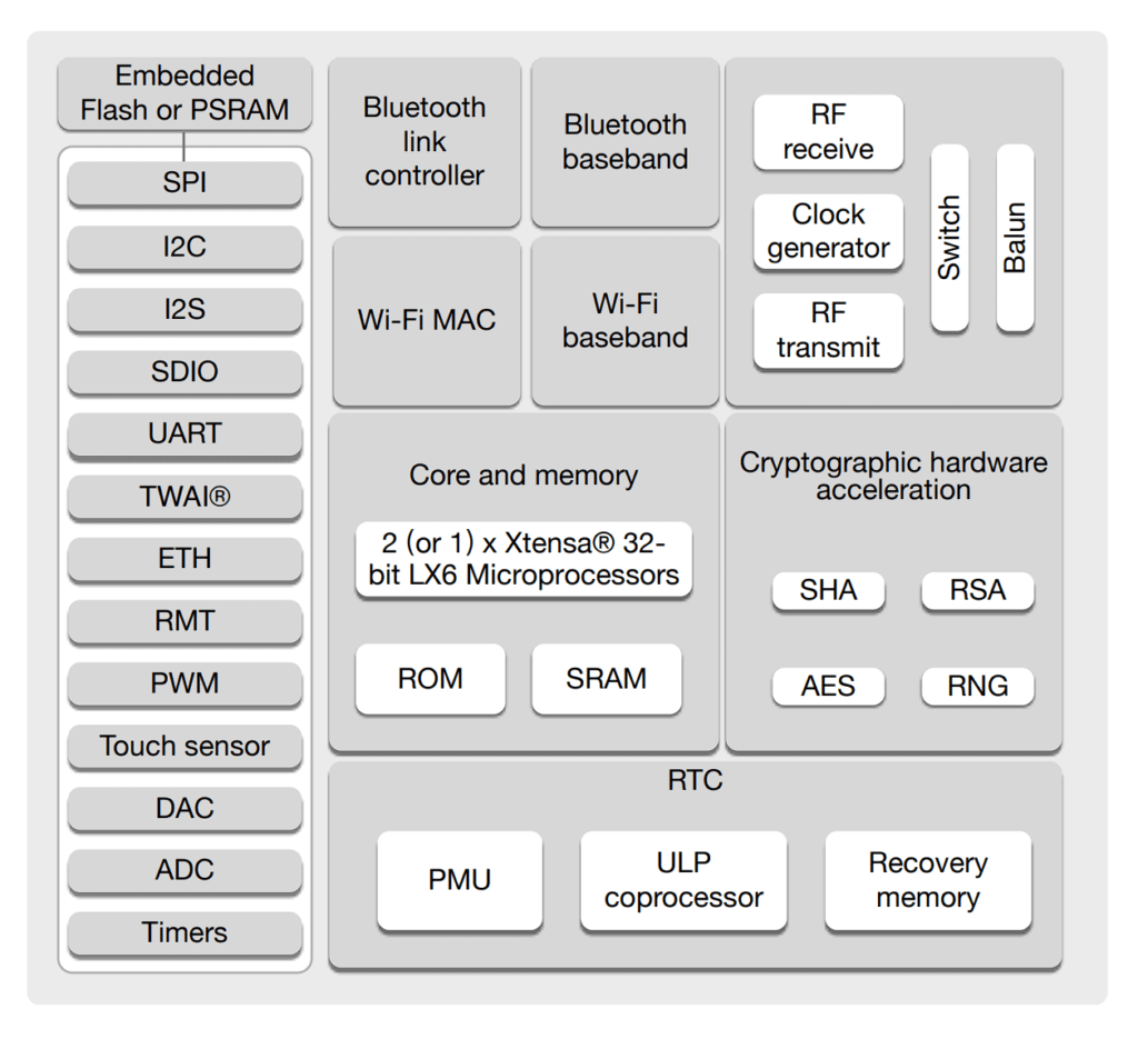
Now is the best time to take a look at the internal block diagram of the ESP32 SoC. As you can see, there are two (1 for some variants) Xtensa 32-bit LX6 microprocessor cores inside the SoC. But every other resource is shared. For example, both cores share the same ROM and SRAM space. This is also true for other peripherals. Both cores can access any peripherals it wants to. But if that is the case, then wouldn’t there be conflicts if one core tries to do some operation with one peripheral and the other core tries to do something else with the same thing? Yes, such a situation can arise in a multi-core environment. For that reason, it is your responsibility as a programmer to write conflict-free code when you are developing applications that require parallel tasks running on multiple cores. Don not be deterred though. There are enough tools and techniques to help you write clean and efficient code for your multitasking applications.
One example of a resource-sharing conflict in a multi-core environment is that of a race condition that occurs during memory access. Suppose we have a memory location with an address 0xF00. We can write two parallel tasks; both of them will try to write a random number to that location and read it afterward. So what happens when one task is writing a value and at the same time the other task is also trying to do the same? Which task gets the chance to write to the memory location? The answer is undefined. That means, we can not predict which one of the tasks gets to write to the memory location because they both are racing to achieve the same.
Race conditions give rise to weird bugs that may not show up during normal testing. So whenever you need to share a variable, object, function, or peripheral between tasks, make sure that only one task accesses the resource at a time. The accessing task must also leave the resource in a determined state after the operation. But how do we do it? Read about it in the next section.
Task Synchronization
Whenever we need to share a resource or make two tasks/processes communicate with each other, we need a mechanism to prevent both tasks from accessing and modifying the resource at the same time. When a task accesses a resource we need to signal all other tasks that the resource is being used at the moment. This is called task synchronization. There are two techniques to achieve this; Mutex and Semaphore. Mutex stands for “Mutual Exclusion”. A mutex is simply a shared variable that is always accessed through atomic operations. What is an atomic operation you ask? It’s a way of executing a sequence of instructions without anything interrupting the operation until it finishes. A mutex variable can remain in two states; locked and unlocked (0 or 1). You can think of it as a boolean variable. It is used to protect a common resource from simultaneous access by multiple tasks. A process/task can acquire a mutex lock by calling a function called acquire(). Once a lock is acquired the task can continue its operations on the object protected by the mutex without worrying about other tasks modifying the resource. If any other tasks try to acquire a mutex lock when it is already in the locked position, the requesting tasks will be put in a wait state called busy waiting. The processes that try to get a lock will repeatedly try to acquire it until they succeed. Busy waiting is also called a spinlock.

The task that initially acquired the lock will release the lock when it finishes all of its operations. Releasing the mutex lock can be done by release(). Now, other tasks waiting to get a lock can acquire it this time. Both acquire() and release() are generic function names used for explaining the concept and the actual names can be platform-specific.
The other type of task synchronization is called a Semaphore which is a method of signaling. The difference between a semaphore and a mutex is that a semaphore acts as a signal like an LED indication while a mutex is a lock that is analogous to a padlock with a key. A semaphore is also a variable shared between the tasks. But it can be in more than two states, unlike mutexes. Semaphores are implemented in two ways; counting semaphores and binary semaphores. A counting semaphore is an integer variable whose value will be initialized with the number of instances of a particular resource to be shared. For example, if you have 10 instances of a data structure then, a semaphore is initialized with the value 10. This means all 10 structs are free at the beginning. Then a task can request one instance of that data and decrement the semaphore variable. The semaphore value will then become 9. When all instances are taken up by the tasks, the semaphore becomes 0. When a task has finished using a resource, it can release the resource and increment the semaphore by 1. If a task requests access when the semaphore is 0, it can either wait until at least one resource is free, or do some other operations without wasting time waiting.
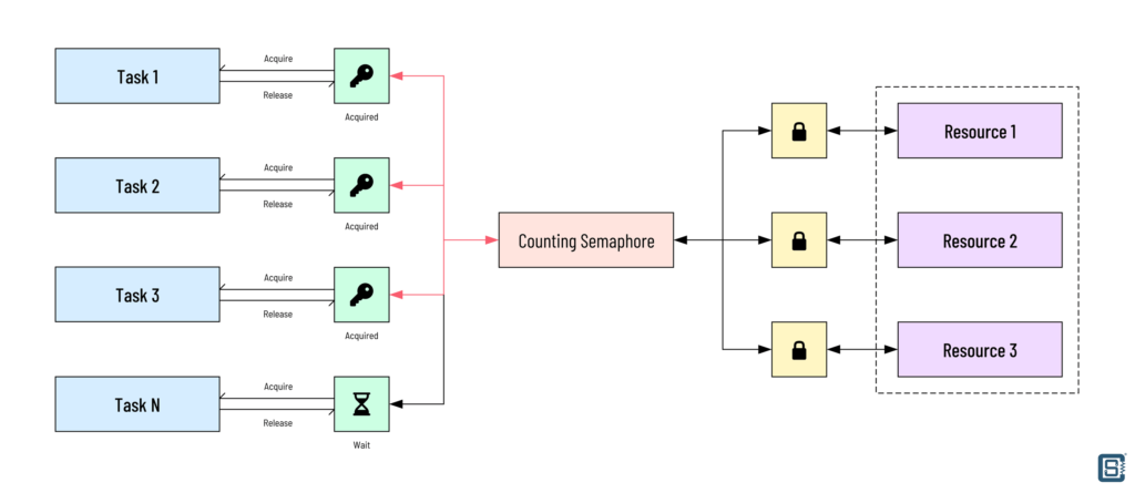
A binary semaphore as the name suggests can only count to 1 or be in a maximum of two states (0 and 1). The difference between a binary semaphore and a mutex is that the binary semaphore only acts as a signal of whether a resource is being used or not but the mutex causes a resource to be locked from other tasks. Both find different use cases. Let’s summarize the concepts of mutex and semaphore if you feel confused.
- A mutex is a mutual exclusion lock that is used when multiple tasks compete for a single resource.
- A mutex can only be in two states; locked and unlocked.
- Mutex causes requesting tasks to “spin” (busy wait) until a resource is available.
- Semaphore is a signaling method. Tasks are free to do something else without wasting time by waiting.
- Semaphores can be in N number of states and the maximum value indicates the total number of resources available.
- Semaphores keep track of resource usage and are good for splittable or multi-instance data.
- Semaphore does not give exclusive access to a resource, but instead gives access to one of the many instances of a resource.
- A binary semaphore indicates the availability of only one instance of a resource.
Examples
Mutex
Let’s see how to write an Arduino sketch to implement a mutex for ESP32 using FreeRTOS.
//================================================================================//
/*
  ESP32 Mutex Example
  Read more at https://circuitstate.com/tutorials/how-to-write-parallel-multitasking-applications-for-esp32-with-freertos-arduino
*/
//================================================================================//

SemaphoreHandle_t xMutex = NULL;  // Create a mutex object

int counter = 0;  // A shared variable

//================================================================================//

// the setup function runs once when you press reset or power the board
void setup() {
  // initialize digital pin LED_BUILTIN as an output.
  pinMode (LED_BUILTIN, OUTPUT);

  Serial.begin (115200);

  xMutex = xSemaphoreCreateMutex();  // crete a mutex object

  xTaskCreatePinnedToCore (
    task1,     // Function to implement the task
    "task1",   // Name of the task
    1000,      // Stack size in words
    NULL,      // Task input parameter
    10,         // Priority of the task
    NULL,      // Task handle.
    0          // Core where the task should run
  );

  xTaskCreatePinnedToCore (
    task2,     // Function to implement the task
    "task2",   // Name of the task
    1000,      // Stack size in words
    NULL,      // Task input parameter
    10,         // Priority of the task
    NULL,      // Task handle.
    0          // Core where the task should run
  );
}

//================================================================================//

// the loop function runs over and over again forever
void loop() {
  digitalWrite (LED_BUILTIN, HIGH);  // turn the LED on (HIGH is the voltage level)
  delay (1000);  // wait for a second
  digitalWrite (LED_BUILTIN, LOW); // turn the LED off by making the voltage LOW
  delay (1000);  // wait for a second
}

//================================================================================//

// this task will periodically lock the mutex, increment the counter by 1 and unlock the mutex
void task1 (void *pvParameters) {
  while (1) {
    if (xSemaphoreTake (xMutex, portMAX_DELAY)) {  // take the mutex
      Serial.print ("Task 1: Mutex acquired at ");
      Serial.println (xTaskGetTickCount());
      counter = counter + 1;  // increment the counter
      Serial.print ("Task 1: Counter = ");
      Serial.println (counter);
      delay (1000);
      xSemaphoreGive (xMutex);  // release the mutex
      delay (100);
    }
  }
}

//================================================================================//

// this task will periodically lock the mutex, increment the counter by 1000 and unlock the mutex
void task2 (void *pvParameters) {
  while (1) {
    if (xSemaphoreTake (xMutex, (200 * portTICK_PERIOD_MS))) {  // try to acquire the mutex
      Serial.print ("Task 2: Mutex acquired at ");
      Serial.println (xTaskGetTickCount());
      counter = counter + 1000;
      Serial.print ("Task 2: Counter = ");
      Serial.println (counter);
      xSemaphoreGive (xMutex);  // release the mutex
      delay (100);
    }
    else {  // if the mutex was not acquired within 200ms
      Serial.print ("Task 2: Mutex not acquired at ");
      Serial.println (xTaskGetTickCount());
    }
  }
}

//================================================================================//
First, we create a mutex object xMutex of type SemaphoreHandle_t. But why does it say “semaphore handle” when we need a mutex? Well, in FreeRTOS both mutex and semaphore are implemented as common sharable routines. This is because of the similarities between both concepts and it makes, from a programmer’s perspective, better abstractions. A semaphore handle can be used to create any type of semaphores or mutex. xMutex is only a handle initialized with a NULL value. It is not usable yet. We define the type of mutex in the setup() function using xSemaphoreCreateMutex().
The counter is a global variable that will act as a common resource. We have two tasks; task1 and task2. Both these tasks can access the counter variable. However, since it is a shared resource and our tasks are running in parallel, we need the mutex mechanism to prevent conflicts such as race conditions.
In the setup() function we also create our tasks by pinning them to core 0. The default loop() will continue to blink our LED as if nothing is happening. Our first task, task1 tries to get a lock on our mutex xMutex with xSemaphoreTake (xMutex, portMAX_DELAY) function call. We need to pass two parameters here; one is our mutex handle and the second is a timeout value. We are using portMAX_DELAY macro which corresponds to an indefinite delay. That means task1 will try to acquire a lock indefinitely until it succeeds. When it gets the lock, it will print some information and increment the counter by 1. The task will then print the value of the counter and wait for 1 second before releasing the mutex lock by calling xSemaphoreGive (xMutex). It will wait for another 100 milliseconds before repeating the whole operation.
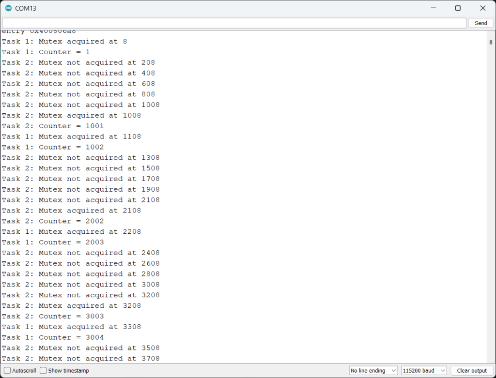
Meanwhile, our second task task2 also competes for the same counter variable. It will also try to get a lock on our mutex xMutex but with a definite timeout of 200 milliseconds specified as 200 * portTICK_PERIOD_MS. If the task can not acquire the lock within that time period, it will momentarily stop trying and print a message instead. Remember that task2 can only acquire the lock if it is in an unlocked state or in other words, not locked by task1. Because task1 takes 1 second to release the mutex, the task2 will have to wait at least 1 second before it can acquire the lock. This will become obvious to you when you see the serial monitor output.
When task1 increments the counter by 1, task2 does it by 1000. This is so that we can easily see who is doing what to the counter. Also, unlike task1, task2 releases the mutex as soon as it is done with the operation. This means that task1 will not need to wait to acquire a lock after 1 second of waiting it already does.
Try uploading the code to your ESP32 board and see the following result in the serial monitor.
Binary Semaphore
Let’s see how we can implement a Binary Semaphore for ESP32 using FreeRTOS and Arduino. Try uploading the following code to your ESP32 board and open the serial monitor.
//================================================================================//
/*
  ESP32 Binary Semaphore Example
  Read more at https://circuitstate.com/tutorials/how-to-write-parallel-multitasking-applications-for-esp32-with-freertos-arduino
*/
//================================================================================//

SemaphoreHandle_t xSemaphore = NULL;  // Create a semaphore object

//================================================================================//

// the setup function runs once when you press reset or power the board
void setup() {
  // initialize digital pin LED_BUILTIN as an output.
  pinMode (LED_BUILTIN, OUTPUT);

  Serial.begin (115200);

  xSemaphore = xSemaphoreCreateBinary();  // Set the semaphore as binary

  xTaskCreatePinnedToCore (
    task1,     // Function to implement the task
    "task1",   // Name of the task
    1000,      // Stack size in words
    NULL,      // Task input parameter
    10,         // Priority of the task
    NULL,      // Task handle.
    0          // Core where the task should run
  );

  xTaskCreatePinnedToCore (
    task2,     // Function to implement the task
    "2000",   // Name of the task
    1000,      // Stack size in words
    NULL,      // Task input parameter
    10,         // Priority of the task
    NULL,      // Task handle.
    0          // Core where the task should run
  );
}

//================================================================================//

// the loop function runs over and over again forever
void loop() {
  digitalWrite (LED_BUILTIN, HIGH);  // turn the LED on (HIGH is the voltage level)
  delay (1000);  // wait for a second
  digitalWrite (LED_BUILTIN, LOW); // turn the LED off by making the voltage LOW
  delay (1000);  // wait for a second
}

//================================================================================//

// this task will periodically release the binary semaphore
void task1 (void *pvParameters) {
  while (1) {
    Serial.print ("Binary Semaphore released at ");
    Serial.println (xTaskGetTickCount());
    xSemaphoreGive (xSemaphore);  // Release the semaphore
    delay (1000);
  }
}

//================================================================================//

// this task will wait for the binary semaphore to be released
void task2 (void *pvParameters) {
  while (1) {
    if (xSemaphoreTake (xSemaphore, (200 * portTICK_PERIOD_MS))) {  // try to acquire the semaphore
      Serial.print ("Binary Semaphore acquired at ");
      Serial.println (xTaskGetTickCount());
    }
    else {  // if the semaphore was not acquired within 200ms
      Serial.print ("Binary Semaphore not acquired at ");
      Serial.println (xTaskGetTickCount());
    }
  }
}

//================================================================================//
First, we will create a semaphore object called xSemaphore with the type SemaphoreHandle_t. This semaphore handle can be used to create any type of semaphore. In the setup() function, we will set this semaphore handle as a binary semaphore with the help of xSemaphoreCreateBinary(). After that, we will create two tasks called task1 and task2. We are pinning both tasks to core 0 but it doesn’t matter. The default loop() simply binks our LED and does nothing else. Since it is a separate task, other parts of our code have no effects on it.
We are using task1 to release or give the semaphore which signals any listening task that the semaphore is available. task1 will repeat this operation every second. The function used to release a semaphore is xSemaphoreGive(). We have to pass our semaphore xSemaphore to that function to release it. The function will set the semaphore to some value representing the released state (this can true for example).
task2 is a separate task running parallel to task1. task2 will check if the semaphore xSemaphore is available using the xSemaphoreTake() function. We need to pass two arguments to this function; the semaphore handle to check and the timeout (as tick count) for the operation. If the semaphore is not acquired within the timeout, the function will return false. This will skip the first if block and print a “Binary Semaphore not acquired” message. If the semaphore gets acquired within the timeout, the message “Binary Semaphore acquired” will be printed along with the timestamp.
xTaskGetTickCount() returns the tick count (a counter value that represents the clock signal count used by the processor). portTICK_PERIOD_MS is a macro that allows specifying time in milliseconds in tick count format. Since we are only releasing the semaphore every second, task2 will only acquire it every second and fail to acquire it in every other case. Try executing the program and you will see the result shown below.
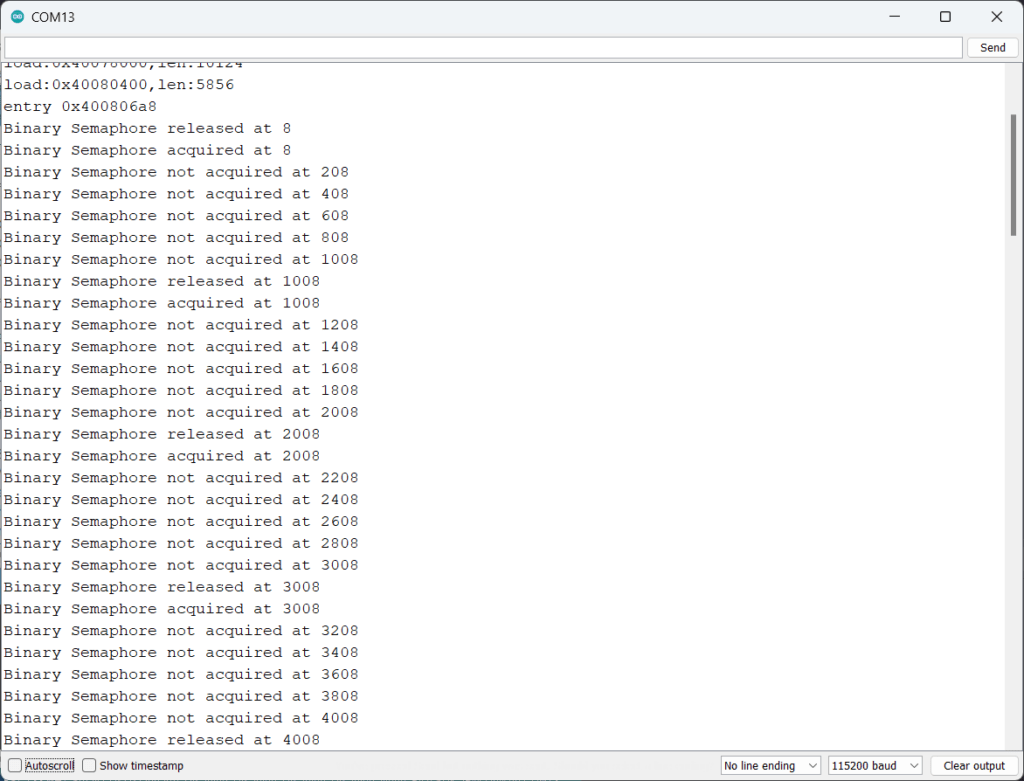
We can see that task2 fails to acquire the semaphore four times before it acquires it the fifth time. The most important thing difference you need to understand is that the binary semaphore we used did not lock any resources from other tasks. Instead, task1 was only signaling task2 that a semaphore was available. That’s the difference between a binary semaphore and a mutex.
Counting Semaphore
Now let’s write an Arduino sketch to demonstrate a counting semaphore on ESP32. Try uploading the following code.
//================================================================================//
/*
  ESP32 Counting Semaphore Example
  Read more at https://circuitstate.com/tutorials/how-to-write-parallel-multitasking-applications-for-esp32-with-freertos-arduino
*/
//================================================================================//

SemaphoreHandle_t countingSem = NULL;  // counting semaphore
SemaphoreHandle_t semFull = NULL;  // semaphore indicating that the counting semaphore is full

//================================================================================//

// the setup function runs once when you press reset or power the board
void setup() {
  // initialize digital pin LED_BUILTIN as an output.
  pinMode (LED_BUILTIN, OUTPUT);

  Serial.begin (115200);

  semFull = xSemaphoreCreateBinary();  // Create a binary semaphore
  countingSem = xSemaphoreCreateCounting (3, 3);  // create a semaphore object

  if (countingSem != NULL) {
    Serial.println ("Semaphore created successfully");
  }

  xTaskCreatePinnedToCore (
    task1,     // Function to implement the task
    "task1",   // Name of the task
    1000,      // Stack size in words
    NULL,      // Task input parameter
    10,        // Priority of the task
    NULL,      // Task handle.
    0          // Core where the task should run
  );

  xTaskCreatePinnedToCore (
    task2,     // Function to implement the task
    "task2",   // Name of the task
    1000,      // Stack size in words
    NULL,      // Task input parameter
    10,        // Priority of the task
    NULL,      // Task handle.
    0          // Core where the task should run
  );
}

//================================================================================//

// the loop function runs over and over again forever
void loop() {
  digitalWrite (LED_BUILTIN, HIGH);  // turn the LED on (HIGH is the voltage level)
  delay (1000);  // wait for a second
  digitalWrite (LED_BUILTIN, LOW); // turn the LED off by making the voltage LOW
  delay (1000);  // wait for a second
}

//================================================================================//

// this will acquire two counting semaphores and wait for a signal from task2
void task1 (void *pvParameters) {
  while(1) {
    if (uxSemaphoreGetCount (countingSem) == 3) { // check if the counting semaphore is free
      if (xSemaphoreTake (countingSem, portMAX_DELAY) && xSemaphoreTake (countingSem, portMAX_DELAY)) { // acquire two semaphores
        Serial.print ("Task 1: 2 semaphores acquired at ");
        Serial.println (xTaskGetTickCount());
        Serial.print ("Task 1: Semaphores left = ");
        Serial.println (uxSemaphoreGetCount (countingSem)); // print the number of semaphores left
        delay (1000);
      }
    }

    if (xSemaphoreTake (semFull, portMAX_DELAY)) {  // wait for signal from task 2
      Serial.println ("Task 1: Semaphore is full. Releasing 2 semaphores..");
      xSemaphoreGive (countingSem); // release the two semaphores
      xSemaphoreGive (countingSem);
      delay (1000);
    }
  }
}

//================================================================================//

// this task will acquire only semaphore
void task2 (void *pvParameters) {
  while (1) {
    if (uxSemaphoreGetCount (countingSem) == 1) {  // check when only 1 semaphore is left
      if (xSemaphoreTake (countingSem, portMAX_DELAY)) {  //try to acquire the semaphore
        Serial.println ("Task 2: Acquiring last semaphore..");
        Serial.print ("Task 2: Semaphore acquired at ");
        Serial.println (xTaskGetTickCount());
        Serial.print ("Task 2: Semaphores left = ");
        Serial.println (uxSemaphoreGetCount (countingSem));
        delay (1000);
        xSemaphoreGive (semFull); // signal that the counting semaphore is full
        delay (1000);
        Serial.print ("Task 2: Releasing 1 semaphore at ");
        Serial.println (xTaskGetTickCount());
        xSemaphoreGive (countingSem); // release the semaphore
      }
    }
  }
}

//================================================================================//
We will first create two semaphore handles; a counting semaphore countingSem and a binary semaphore semFull to signal when the counting semaphore is full. semFull will be set to a binary semaphore using xSemaphoreCreateBinary(). To create a counting semaphore we should use xSemaphoreCreateCounting() and pass two values; the maximum value of the counting semaphore and the initial value. The maximum number can indicate the number of resources you have, for example. In this example, we are setting the maximum value to 3, which means countingSem can only be acquired for a maximum of three times. Trying to acquire beyond 3 will fail.
The initial value can be set to either maximum (3) or minimum (0). For example, if you have a finite number of resources that you want to distribute to your tasks, then you can set it to the maximum value. But if you are counting some events, then you can set the initial value to 0. In both cases, you can use the function uxSemaphoreGetCount() to get the current number of free semaphores.
In task1, we will first check if the counting semaphore count is 3. Since the initial value of countingSem is 3, this check will return true. Then we will take two semaphores from countingSem using the now-familiar xSemaphoreTake(). We will use the maximum timeout portMAX_DELAY for acquiring. Once the two semaphores are acquired, task1 will wait task2 to raise the semFull signal.
Meanwhile, task2 will be checking when the countingSem becomes 1, or in other words when task2 acquired 2 semaphores. So now it’s task2‘s time to acquire the remaining 1 semaphore. After acquiring the last semaphore, task2 will wait for 1 second before raising the semFull signal using xSemaphoreGive. This will signal task1 that all counting semaphores have been acquired. When task1 gets this signal, it takes the semaphore using xSemaphoreTake() and releases the two semaphores it initially acquired. After two seconds, task2 will also release its semaphore. At that instance, countingSem will be completely freed. The whole process repeats again from there.

FreeRTOS Critical Section
So far all our examples and discussions revolved around a calm and predictable environment of sequential and parallel tasks that are easy to picture in mind. The coding was also relatively easy. But there is an important concept we haven’t taken into account yet; interrupts. Interrupts disturb the normal flow of a program and it is applicable to both sequential and concurrent programming. Interrupt service routines (ISR) are designed to respond as fast as possible to an asynchronous event (the time when it happens is not predictable). Interrupt services must also finish their operations faster. Depending on the priority of the interrupt, a set of currently running tasks are deferred until the interrupt routine is completed. Interrupts are already complicated in a single-core environment and it gets even more complicated in a multi-core environment.
Interrupts can also interrupt FreeRTOS tasks depending on how they are configured. If so what happens when you have a piece of code that is so critical that you don’t want the interrupts to block it even for a short time? Disabling the interrupts is one method, but that defeats the purpose of using interrupts. To solve the problem, FreeRTOS allows us to define critical section code using taskENTER_CRITICAL() and taskEXIT_CRITICAL() macros. You can call taskENTER_CRITICAL() just before your critical code and then call taskEXIT_CRITICAL() once done. Always make sure that your critical section code is as short as possible. Otherwise, it will adversely affect the interrupt response time.
Let’s see how you can write a critical section code for ESP32.
//================================================================================//
/*
  ESP32 Critical Section Example
  Read more at https://circuitstate.com/tutorials/how-to-write-parallel-multitasking-applications-for-esp32-with-freertos-arduino
*/
//================================================================================//

portMUX_TYPE taskMux = portMUX_INITIALIZER_UNLOCKED;  // critical section mutex

int counter = 0;  // A shared variable

//================================================================================//

// the setup function runs once when you press reset or power the board
void setup() {
  // initialize digital pin LED_BUILTIN as an output.
  pinMode (LED_BUILTIN, OUTPUT);

  Serial.begin (115200);

  xTaskCreatePinnedToCore (
    task1,     // Function to implement the task
    "task1",   // Name of the task
    1000,      // Stack size in words
    NULL,      // Task input parameter
    10,         // Priority of the task
    NULL,      // Task handle.
    0          // Core where the task should run
  );

  xTaskCreatePinnedToCore (
    task2,     // Function to implement the task
    "2000",   // Name of the task
    1000,      // Stack size in words
    NULL,      // Task input parameter
    10,         // Priority of the task
    NULL,      // Task handle.
    0          // Core where the task should run
  );
}

//================================================================================//

// the loop function runs over and over again forever
void loop() {
  digitalWrite (LED_BUILTIN, HIGH);  // turn the LED on (HIGH is the voltage level)
  delay (1000);  // wait for a second
  digitalWrite (LED_BUILTIN, LOW); // turn the LED off by making the voltage LOW
  delay (1000);  // wait for a second
}

//================================================================================//

// this task will periodically lock the mutex, increment the counter by 1 and unlock the mutex
void task1 (void *pvParameters) {
  while(1) {
    Serial.print ("Task 1: Trying to increment the counter at ");
    Serial.println (xTaskGetTickCount());

    portENTER_CRITICAL (&taskMux);  // lock the mutex (busy waiting)
      counter = counter + 1;  // increment the counter
      Serial.print ("Task 1: Counter = ");
      Serial.println (counter);
    portEXIT_CRITICAL (&taskMux); // unlock the mutex

    delay (1000);
  }
}

//================================================================================//

// this task will periodically lock the mutex, increment the counter by 1000 and unlock the mutex
void task2 (void *pvParameters) {
  while (1) {
    Serial.print ("Task 2: Trying to increment the counter at ");
    Serial.println (xTaskGetTickCount());

    portENTER_CRITICAL (&taskMux);  // lock the mutex (busy waiting)
      counter = counter + 1000;
      Serial.print ("Task 2: Counter = ");
      Serial.println (counter);
    portEXIT_CRITICAL (&taskMux); // unlock the mutex

    delay (500);
  }
}

//================================================================================//
The method for creating a critical section mutex for ESP32 is called portENTER_CRITICAL which is equivalent to taskENTER_CRITICAL(). Similarly, there is portEXIT_CRITICAL that is equivalent to taskEXIT_CRITICAL(). In order to use the macros, we need to pass a mutex object. It can be created with the data type portMUX_TYPE. We create a mutex object called taskMux and initialize it with portMUX_INITIALIZER_UNLOCKED which tells the mutex is free/unlocked initially. We have the rest of the code similar to our previous mutex example. Since counter is our shared variable, we can access it under a critical section to prevent other tasks from interfering. So just before accessing the counter variable we call the portENTER_CRITICAL (&taskMux) function. Notice that we are passing our mutex object. Any task which is also trying to acquire the same mutex will have to wait until we are done. Also, this allows us to create multiple mutexes and thus critical section code in many places.
After we are done modifying the counter value, we will exit the critical section by calling portEXIT_CRITICAL (&taskMux). At this time, other tasks can acquire a lock to the mutex. Interrupts are momentarily suspended when the processor enters a critical section code. It is extremely useful for sharing hardware registers in a multi-core environment without conflicts. See the output below.

Since task1 waits for 1 second and task2 only 0.5 seconds after their critical section operations, task2 gets to increment the counter twice consecutively.
What’s Next?
There are still so many things to explain in detail, such as Watchdog Timer, Interrupts, Queues etc. But I think for this tutorial we have explained enough things to help you write parallel multitasking applications taking advantage of the dual cores of ESP32 and managing task synchronization. You can find better and more detailed tutorials on these topics all over the internet. We have two suggestions; one is https://techtutorialsx.com/ from Nuno Santos and https://esp32tutorials.com/. Both these websites have a long list of tutorials covering different features of the ESP32. Finally, you can read everything about using FreeRTOS with ESP32 from the official documentation. If you run into issues, you can always try debugging your code with the official ESP-Prog debug probe. Check out our following tutorial to learn more. Happy coding 😀
Debugging ESP32 Arduino & ESP-IDF Projects using ESP-Prog and PlatformIO
Links
- Semaphores and Mutexes – FreeRTOS
- Concurrency vs Parallellism
- ESP32 Tutorials – https://techtutorialsx.com/category/esp32/
- Difference between binary semaphore and mutex
- SemaphoreHandle_t and critical section – the difference
- Critical section code – FreeRTOS
- FreeRTOS in 20 Minutes
Short Link
- Short URL to this page – https://circuitstate.com/pmulesp32


Hi,
Thanks a lot for your tutorial. However, when I ran the code of the critical section example, my ESP32 repeatedly reset and could not finish printing out the counter value for task 2. Is it because the program in the critical section takes too much time to process? Because when I removed the
Serial.print()inside the critical section, the code worked fine.Thanks for your feedback. We just ran the code on a FireBeetle-ESP32E board and we observed the same problem. We are using the latest versions of all packages. I think something must have changed in the packages after we published the post. We are currently trying to find out what the issue is.
The error message we got included the following line.
rst:0x8 (TG1WDT_SYS_RESET),boot:0x13 (SPI_FAST_FLASH_BOOT)This indicates that the
Timer Group 1 WDTwas triggered. We tried disabling theSerial.print()lines ontask2and it was working correctly. So you are right, theprint()function was taking more time for some reason, and triggering the watchdog.In actual applications, we must keep the critical section code as short as possible and avoid calling functions with busy waits. Since the code provided is only an example, let’s ignore the error for now.
Hi,
src/main.cpp: In function 'void setup()':src/main.cpp:13:5: error: 'loop2' was not declared in this scope
loop2, // Function to implement the task
^~~~~
src/main.cpp:13:5: note: suggested alternative: 'loop'
loop2, // Function to implement the task
^~~~~
loop
*** [.pio\build\lolin_s3_mini\src\main.cpp.o] Error 1
What is missing and how did you get it working in platformio without
#include#include
?
Hi Tom. The header files reqired are automatically included by the compiler when the Arduino sketch is converted to a proper C/C++ file. Regarding the error you are getting, please check if you have selected the right board type and platform in the configuration.
Also, if you are using PlatformIO, you need to include the forward declarations of all functions before all of the function definitions. Otherwise, PIO will throw errors.
I was wondering if the shared variables in the code segments should be declared as volatile and why not if they do not need to be?
The
volatilekeyword is used to prevent the compiler from optimizing away the variable by using cached copy instead of directly reading from memory every time. This is useful when declaring variables that are directly connected to an underlying asynchronous hardware logic, for example GPIO register of a microcontroller. The value of the GPIO register can change any time due to external inputs and the program must always read it directly from memory instead of using a recent copy of it. But in a multi-threaded and multi-core environment, it is not necessary to use thevolatilekeyword unless it is a hardware register. Usingvolatiledoesn’t give access protection in a multi-threaded environment. Instead, we must always use mutexes and semaphores to synchronize access to shared variables between tasks, just like we have shown.Great article. I wish it had gone a bit further and covered when things like WiFi is enabled.
I have a timer function running every 20 microseconds (also tried a interrupt function on state change of a GPIO pin) to measure the state and duration of a QAM_RX 433 receiver. When the message is received it displays on the serial port.
Works a treat until I run
WiFi.begin()and then my function doesn’t trigger (all the time).For now I’ve gone back to the Arduino Nano doing the 433 stuff and then via Serial talking to the ESP32 so via WiFi it can update a MQTT queue. I was hoping to do it all in the ESP32 but I just don’t seem to be able to get it working.
Hi Ian. Thanks for the feedback. Does your timer function utilize one of the ESP32’s hardware timers? If not, for precise and deterministic timing, we recommend using a hardware timer. You can load the timer with a preset and wait for the interrupt to call your function.
Regarding the issue of Wi-Fi interrupting your timing function, could you please confirm if you are using the same or different core for your timer function? ESP32 has two cores and Core 1 is used by the Wi-Fi and Bluetooth stack by default. Running timing critical functions in the same core when Wi-Fi is running can cause issues. We suspect that to be the issue. But we can’t be sure without seeing your code. ESP32 and its software framework is very complex, and so if we do not do things the right way, things will fail. Please let us know if you are able to narrow down the problem.
Hi
Thanks for your reply. I’ve put my example code on github for you to have a look at. Welcome any suggestions.
I’m rapidly coming to the conclusion I can’t do 433Mhz stuff and WiFi stuff on the same ESP32. I might go back to the Arduino Nano for 433Mhz and let it talk to the ESP32 via serial. 🙁
https://github.com/ichilver/esp32-433-wifi