Getting Started with Arduino – Beginner’s Tutorial to Open-Source Hardware Prototyping with Arduino Uno
Learn electronics hardware prototyping and coding with the most popular Arduino open-source microcontroller platform. Learn how to write your first program and upload it to the Arduino Uno board.
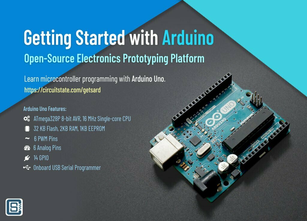
Arduino is probably the most familiar term among electronic hardware engineers and geeks all over the world. And that is for a good reason. Arduino is the most prominent revolution that happened in the adoption of open-source hardware and embedded software. Arduino made access to microcontroller hardware easier and more friendly to even the non-engineering folks who could then leverage the power of tiny computers for their creative projects. Today Arduino is a very mature open-source hardware ecosystem with hundreds of supported microcontroller boards, shields, modules, software libraries, and software tools. Manufacturers who were once reluctant to the idea of open-source are now embracing its growth and wanting a slice of it. Arduino is currently being utilized in the fields of STEM Education, IoT, Industry 4.0, and more. Arduino Pro is a subsidiary of Arduino that caters to the needs of industrial customers along with other commercial-scale services such as Arduino Cloud.
In this post, we will learn what Arduino is, how it works, and how you can get started with the awesome hardware prototyping platform. You may be a complete beginner at electronics and that’s okay. What makes Arduino cool is that you can grab an Arduino board, a breadboard, a bunch of wires, and a few LEDs and get things working without much prior knowledge. A little knowledge of basic electricity will be good. But don’t worry, you can learn everything on the fly. You might encounter strange technical terms further in this article, that we might not explain immediately. But at the end of the article, we would have explained most of the things.
We can develop embedded firmware for you
CIRCUITSTATE can develop embedded firmware for any microcontroller/microprocessor including 8051, PIC, AVR, ARM, STM32, ESP32, and RISC-V using industry-leading SDKs, frameworks, and tools. Contact us today to share your requirements.

What is Arduino?
What comes to mind when hearing Arduino can be different for different people. For some it is the greenish-blue microcontroller boards, for some, it is the IDE and for others, it is the Arduino-style code. Well, Arduino is all of it and more.
- Arduino is a company – Arduino is a company with offices in Turin, Italy, and Somerville, USA.
- Arduino is a trademark – Arduino is a registered trademark of Arduino and you must follow the legal requirements when using the word or logo anywhere. More details can be found here.
- Arduino is an IDE – The Arduino IDE is the standalone cross-platform software that lets you write code and upload it to Arduino boards.
- Arduino is a collection of microcontroller boards – Official Arduino-supported boards are collectively called “Arduino boards”. Unofficial Arduino-supported boards are called “Arduino-compatible boards”.
- Arduino is hardware code – This mainly includes the bootloaders used by Arduino-supported microcontrollers.
- Arduino is a set of software libraries – The libraries simplify and unify access to complex hardware peripherals found inside a modern microcontroller. The libraries allow near-seamless porting of Arduino code to different hardware platforms.
- Arduino is a syntax – The Arduino code uses a friendly and descriptive syntax for writing embedded code. In the backend, Arduino code is standard C/C++.
- Arduino is an online store – This is where you can buy official Arduino products from. You can also buy official Arduino products from authorized distributors all over the world. You can find a list of them here.
- Arduino is a community – Whether you are enjoying the benefits of Arduino or contributing to it, you are part of the community. Arduino is a community of makers, hobbyists, students, and professional engineers alike, sharing common interests in open-source hardware.
History of Arduino
History can be complicated with so many intertwined events and facts. Arduino’s history is also the same. Wikipedia is probably the best place you can find peer-verified information about the history of Arduino. But let’s give you a gist. The forerunner of Arduino is Wiring (official site), an open-source programming framework for microcontrollers, created by Hernando Barragán as his Master’s thesis at Interaction Design Institute Ivrea, Italy. Wiring IDE was based on the Processing graphical framework created by Casey Reas and Ben Fry. Interactive design is the creation of artwork by incorporating interactive components that may self-manipulate or be manipulated by an observer. Interactive design uses mechanical, electrical, or computing elements to add interactive features to artworks. The goal of Wiring was to make it easier to use low-cost microcontroller hardware for creating such art. Later, Massimo Banzi and others created a fork (creating a variant of something) of the Wiring platform and named it Arduino. The name Arduino comes from a bar in Ivrea, Italy which is named after Arduin of Ivrea, an Italian king. A comprehensive history of Wiring and Arduino can be found in this post by Hernando Barragán.
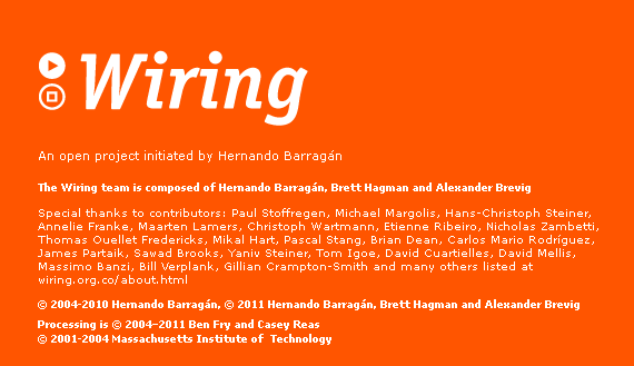
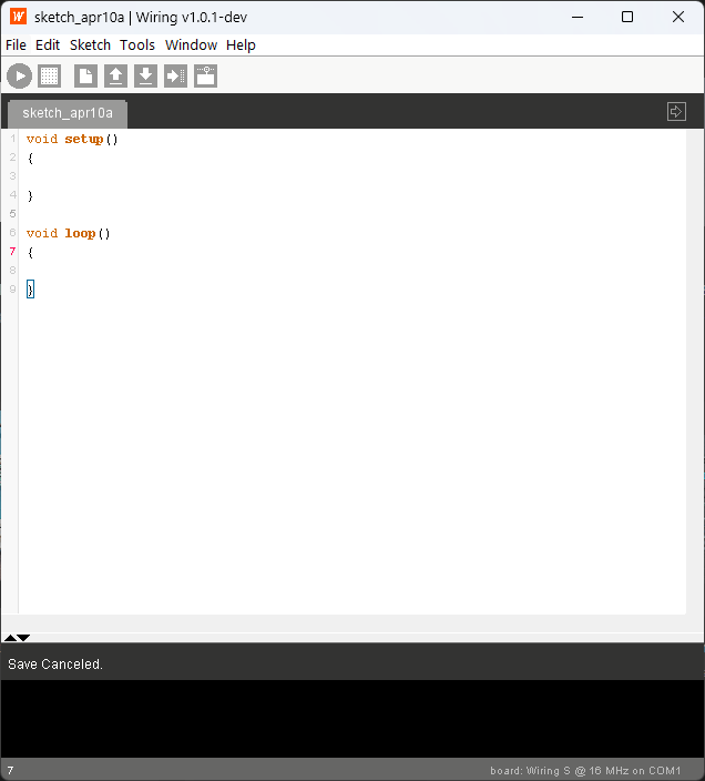
You will find striking similarities between these three frameworks, including the interface, development language (Java), and the style of writing code. Most of the features of Arduino come from Wiring. But Wiring is no more being maintained but Arduino continues to improve to this day with the help of the active community.
Why Arduino?
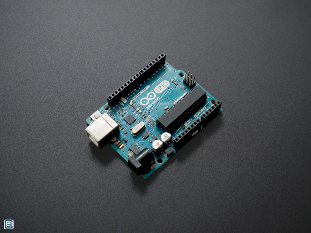
The time Arduino arrived at the hardware scene was when microcontrollers could only be used with costly and complex development kits and programmers produced by manufacturers. These tools along with their complementary software suits were mostly proprietary and targeted at experienced engineers to develop commercial applications. This means it was difficult and unaffordable for an average student/hobbyist/educator/artist to get their hands on microcontroller hardware. Hardware manufacturers never cared about making their products hobbyist-friendly because they found no commercial value in it. But geeks around the world kept tinkering with hardware in unique ways and creating affordable tools such as programmers and development boards. But there was a lack of unity and direction among them.
Arduino (or originally Wiring) simplified microcontroller programming and hardware prototyping, and it kick-started a revolution. The explosion of the internet fueled the popularity and adoption of Arduino. Suddenly, anyone could use low-cost microcontrollers in their projects without spending money on expensive development kits or programmers. For example, the official ATMEL-ICE programmer that can be used to program and debug ARM and AVR family controllers costs around Rs.13,000. That’s way more than an average hobbyist could spend. But at the same time, a fully standalone Arduino Uno board costs only a tenth of it.
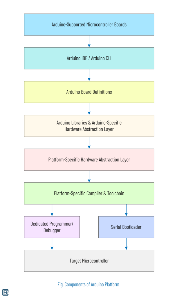
The success of Arduino comes from the open-source community contributing to it. Some people created new microcontroller boards that could be programmed via the Arduino IDE. Some created pluggable extension boards called shields that added new features to the original boards. Some developers ported other microcontroller architectures and families to be compatible with Arduino. Others created Arduino-compatible libraries for every sensor or display you could find. At the same, Arduino as a company kept adding new boards and microcontrollers to their official offerings. Arduino maintained the standards and guidelines for new contributions to the platform. In addition to individual contributors, hardware companies also started recognizing the potential of open-source projects and started officially delivering products that meet the requirements specified by Arduino and other open-source projects. Companies like Microchip, ST Microelectronics, Intel, Texas Instruments, Espressif, etc. are some examples.
What is Open-Source?
The world is not hundred percent fair and it is also highly competitive. In such a world, it becomes obvious to protect a new idea or an invention, to prevent someone unfairly claiming rights for it and taking benefits. This can be accomplished through different methods, such as patenting, copyrighting, etc. You can also keep things secret or keep someone legally restrained from disclosing something. This proprietorship of ideas allows only you to commercialize and make a profit from it. This applies to computer source code and hardware designs. A proprietary design is referred to as closed-source since you can not get to see the internals of that design. For example, Microsoft Windows is a closed-source operating system. You can not get a copy of the source code even if you wanted. You can not see it, you can not modify it nor you can redistribute it on your own. Doing so can end you up in prison or paying hefty fines.
In contrast, Open-source is a philosophy and a social movement of embracing openness and freedom relating to creative works. Openness means you can openly share your creative works and not sue anyone for seeing them. Others will be able to get a copy of the design and understand how something works. As the creator, you must explain how something was created, how it works, and how it can be improved. There may be a person who can come up with a better design than what you have created. But you seldom know who that is. Sharing an idea openly with others means, there is a higher chance that you can find the right individuals who can improve what you have created. And for all of that, you will be credited with the right attributions for creating something in the first place, if you wanted. Openness in creativity brings talent from places that you can not find otherwise. It is the best way of improving anything.
Openness alone is not enough for crowdsourcing ideas, there should also be freedom. Freedom is the freedom to copy, freedom to modify, and freedom to redistribute something someone has shared. It allows ideas and creations to propagate freely, and progressively become better. You will not be sued for modifying something and distributing it. The aspect of freedom in open-source is usually shortened to “free” such as in Free Software Foundation. Free doesn’t mean free of charge.
Open-source is also a legal framework consisting of many types of open-source licenses. The licenses prevent misuse and provide legal solidity for prosecuting any misuse. Open-source licenses are free of charge to obtain and use. The licenses are written in a way that sounds in accord with the law. By including an open-source license in the original source of your work, you are protecting it from misuse.
Arduino is an open-source platform released under GNU GENERAL PUBLIC LICENSE Version 2. The software may also include other sources released under a different open-source license such as MIT. You can see and get a copy of most of the software components and hardware designs created by Arduino. You can add improvements to them by contributing changes. You can create a fork of a design and name it something new and redistribute it, as long as you follow the obligations to the original license.
Buying an Arduino Board
There are so many options when it comes to buying Arduino-supported boards. You can buy the official Arduino boards from either the official store or one of the authorized distributors in your country. Buying from an authorized seller is the easiest option because you can pay in the local currency, shipping will be fast and you will not have to worry about import duties or anything. You can find a list of Arduino-authorized distributors here. Following are the authorized distributors in India.
- Robu.in
- rhydoLABZ
- Circuitects Electronic Solns Pvt. Ltd.
- Duck Learning
- Elementz Engineers Guild Pvt Ltd
- RAJGURU ELECTRONICS I PVT. LTD.
- Smapptech Systems Pvt Ltd
- ThingBits Electronics Pvt. Ltd.
- TIF Labs Pvt Ltd
Buying from the official distributor means you always get the original product, not the counterfeits. A counterfeit Arduino board is one that is made to look like the official board and is sold at the same price as the official one. Such counterfeits will also illegally use the Arduino trademark on them. Try not to fall for such false advertisements.
But you should also be aware of Arduino clones. These are boards that look and function the same as the official Arduino boards but cost much less. The cost is reduced due to the use of cheaper quality components and the production magic of China. The clone boards will not have the Arduino logo or other trademarks. These boards are manufactured by respecting the trademarks.
But why you should buy the official boards and why does it cost much more? Official Arduino boards are manufactured in Italy and USA. The production cost is higher at these places. Also, official Arduino boards use high-quality components which also makes the boards cost higher. This means that official Arduino boards will be higher quality and more reliable than cheaper clones. Buying an official Arduino board also supports Arduino. You can buy both official boards and clones from the distributors listed before.
Now, which model of Arduino board should you buy? We recommend buying the Arduino Uno board. It is the first microcontroller board from Arduino and is the most popular one. You can buy either the official one or a clone.
Because we are going to demonstrate a few basic examples, you could also order the following items with your board.
- Solderless Breadboard
- Dupont Jumper Cable Set
- Resistor Assortment Kit
- 5mm Blue LED
- 1k Ohm Trimpot Trimmer Potentiometer
These items also come as a bundle that includes everything you need to get started. If the official kits are too expensive for you, you can find lower-cost kits at local vendors.
What’s Inside a Microcontroller?
A microcontroller is a small programmable computer chip. The chip processes computer programs written in binary (0s and 1s) language. Such a chip is called a Central Processing Unit (CPU), microprocessor, or simply a processor. Your laptop or desktop has a central processor. Your smartphone has a main processor. However there are many differences between a microprocessor and a microcontroller.
| Microprocessor | Microcontroller |
|---|---|
| High computing power | Low computing power |
| High clock speeds | Low clock speeds |
| External program storage | Internal/external program storage |
| External RAM | Internal RAM |
| High power consumption | Low power consumption |
| Complex instruction set | Simpler instruction set |
| No communication peripherals | Internal communication interfaces |
| Requires operating system | No need of an operating system |
| Non-real-time behavior | Real-time behavior |
| Complex architecture | Simpler architecture |
| Higher transistor count | Lower transistor count |
| Mainly used for data-intensive applications | Mainly used for control applications |
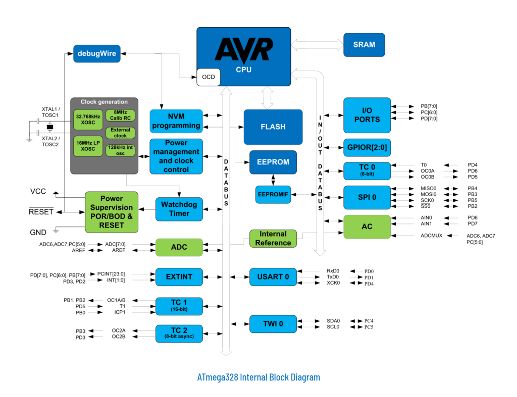
Arduino Uno board uses an 8-bit microcontroller called ATmega328P. The internal block diagram of ATmega328P is shown above. The Flash is actually where a microcontroller stores programs. Flash is a NOR or NAND-based non-volatile memory which is the same thing inside your memory cards. Random Access Memory (RAM) is on the other hand a fast memory used to store data temporarily during calculations. RAM is a volatile memory which means the contents of it are lost when power is disconnected. The type of RAM used in ATmega328P is Static RAM (SRAM) made of transistors. ATmega328P also has an EEPROM (Electrically Erasable Programmable Read-only Memory) where you can store data permanently.
The AVR microcontroller also has communication peripherals (SPI, UART, I2C, etc.), timers, ADC, and much more. All of these peripherals can communicate through the internal data bus. It also has power and clock management circuits inside. A detailed explanation of the working of a microprocessor/microcontroller is beyond the scope of this post. But this article is worth reading.
Arduino Uno
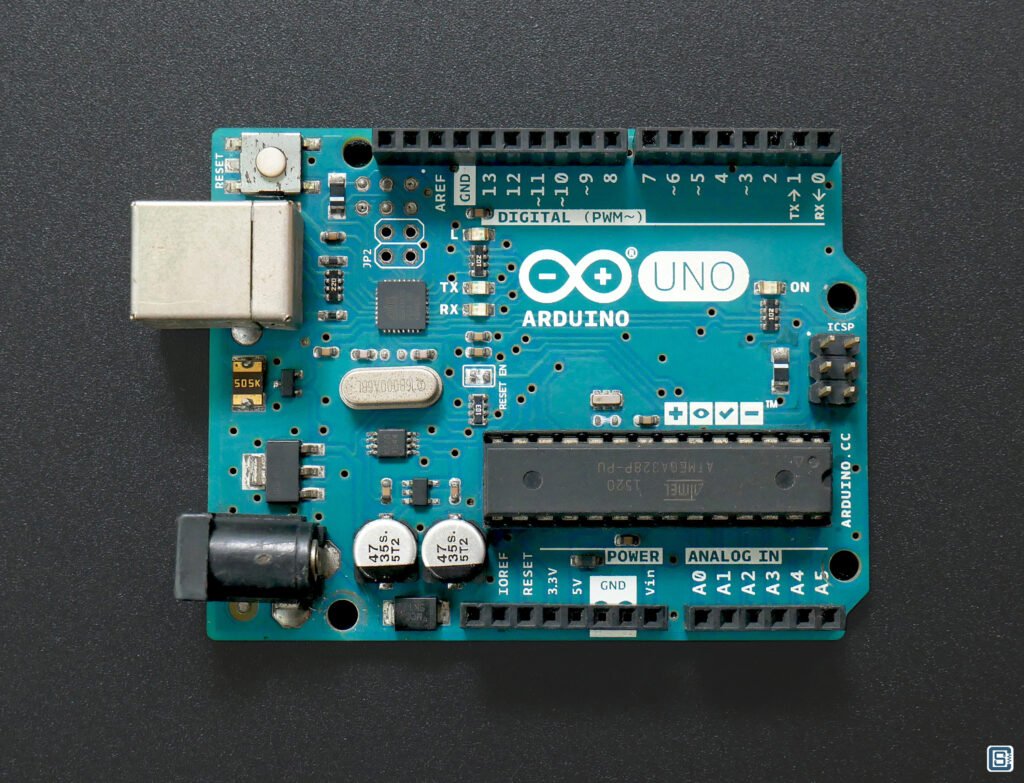
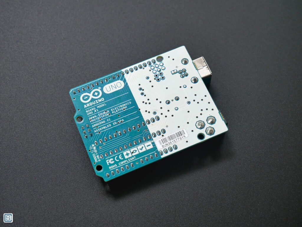
Uno means “one” in Italian. Uno was the first Arduino board. The Arduino Uno is a visual synonym for the word “Arduino” since the board is the most recognized. Uno features an 8-bit AVR microcontroller called ATmega328P. AVR is a very popular RISC (Reduced Instruction Set Computer) microcontroller family developed by Alf-Egil Bogen and Vegard Wollan as students. AVR stands for Alf and Vegard’s RISC processor. RISC is a type of processor architecture that simplifies silicon design. A simple architecture reduces the number of transistors you need to embed on a silicon chip. This reduces the cost as well as makes it more efficient. Moreover, the instruction set (a set of commands that you can ask a CPU to execute) is also simplified and most instructions will complete execution in just one clock cycle (a basic unit of time used by a CPU). All these translate to the reasons why ATmega328P was chosen for Arduino Uno. It is low-cost, feature-rich, has good throughput (computing power), consumes very little power, and is supported by an open-source toolchain (AVR-GCC). ATmega328 is a variant of ATmega8. The number 32 indicates the flash memory capacity of 32 Kilobytes. Let’s see what are all the features of this AVR microcontroller.
ATmega328P Technical Specs (28-pin DIP)
| Specification | Value |
|---|---|
| CPU Speed (MIPS/DMIPS) | 20 (at 20 MHz) |
| Program Memory Type | Flash |
| Program Memory Size | 32 KB |
| SRAM | 2 KB |
| Data EEPROM | 1 KB |
| 8 Bit Digital Timers | 2 |
| 16-bit Timers | 1 |
| PWM Channels | 6 |
| GPIOs | 23 |
| ADC Channels | 8 |
| Max ADC Resolution | 10 Bits |
| Number of Comparators | 1 |
| SPI | 2 (1 shared with USART) |
| USART | 1 |
| I2C | 1 |
| Temp. Range | -40 to 85 °C |
| Operating Voltage Range | 1.8 – 5.5 V |
| Sleep Modes | 6 (Idle, ADC Noise Reduction, Power-save, Power-down, Standby, and Extended Standby) |
| Pin Count | 28 |
The latest design revision of Uno is R3. Make sure you buy the latest model. The IC package of ATmega328P used in Uno is a 28-pin DIP (Dual-Inline-Package). This IC is inserted into a 28-pin IC socket. This makes it easy to remove the IC from the Uno board and use it on a standalone project or be used on a breadboard.
Even though ATmega328P can run at a maximum of 20 MHz, Uno uses a 16 MHz crystal on it. This allows the processor to execute 16 Million Instructions per Second (MIPS). An instruction can, for example, add or subtract two numbers together. So that is a lot of computing power for a small chip. There is a 32 KB of Flash memory to store instructions. The instructions are collectively called a program or firmware. The program memory can be erased when you want to update the firmware. The flash memory is non-volatile which means the contents of the memory are not lost when the power is disconnected. 2 KB is available for SRAM (Static Random Access Memory). SRAM is the working memory of the microcontroller, where data is stored temporarily during calculations. SRAM is much faster than Flash memory. It is also volatile, which means memory contents are lost when the microcontroller is disconnected from power. A microcontroller needs both Flash and RAM to work. In addition to the Flash and SRAM, ATmega328P also has 1 KB of EEPROM (Electrically Erasable Programmable Read-Only Memory). EEPROM is a type of non-volatile memory where you can permanently store data while the program is running.
A microcontroller is typically used for electronic control applications, for example, say a washing machine or an induction cooktop. The microcontroller needs to take inputs from sensors and buttons, and carry out actions based on the conditions. For example, there will be a temperature sensor on your induction cooktop that can measure the temperature of the cooking pan. The microcontroller can read the temperature sensor. When the temperature rises above a safe threshold, the microcontroller will turn off the heating to protect the equipment. Similarly, the microcontroller can accept different kinds of inputs. ATmega328 has many such input and output features. There are 23 GPIO (General Purpose Input-Output) pins that can accept digital inputs and produce digital outputs. A digital signal can only remain in either of the two states; HIGH (represented by +5V) or LOW (represented by 0V). All GPIO pins can act as digital inputs or outputs. We will later see how you can produce digital signals with Arduino Uno.
ATmega328P can also measure voltages directly with the help of an ADC (Analog to Digital Converter). You can measure any voltages between 0 to 5V with a precision of 0.0048V. The precision is determined by the bit resolution of the ADC, which is 10 bits for ATmega328P. In addition to the ADC, ATmega328P also has PWM (Pulse Width Modulation) outputs. PWM is a type of digital signal that can keep a digital output pin ON/OFF for specific time periods. PWM signals can be used to control the brightness of an LED or the speed of a motor. This is analogous to producing a variable analog voltage.
The microcontroller can also communicate with other devices, such as another microcontroller, by sending or receiving digital signals. ATmega328P has UART (Universal Asynchronous Receiver Transmitter), SPI (Serial Peripheral Interface), and I2C (Inter-Integrated Circuit) interfaces for communication.
ATmega328P Pinout
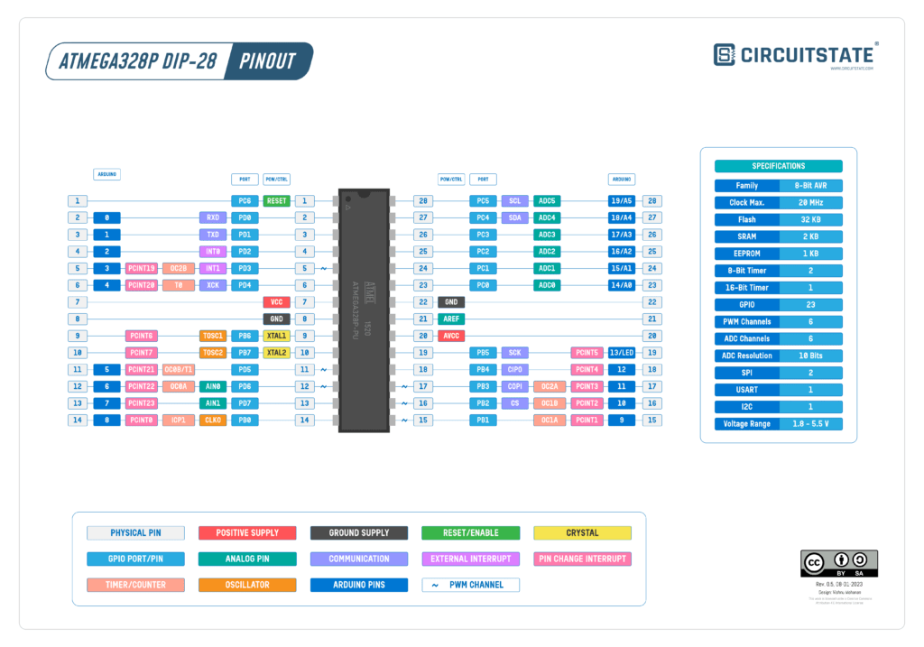
ATmega328P DIP-28 – Pinout Diagram & Arduino Pin Reference
Uno Pinout
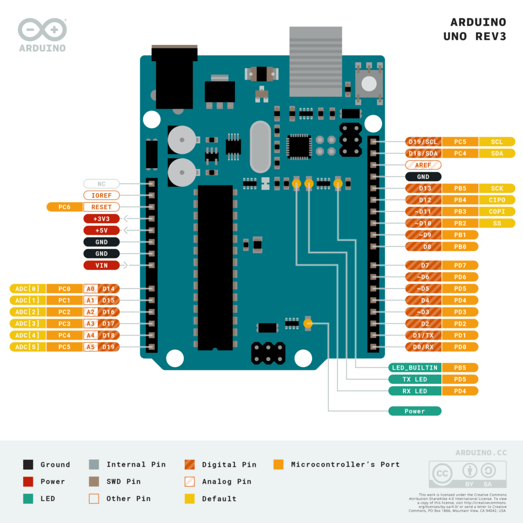
Uno Board Topology
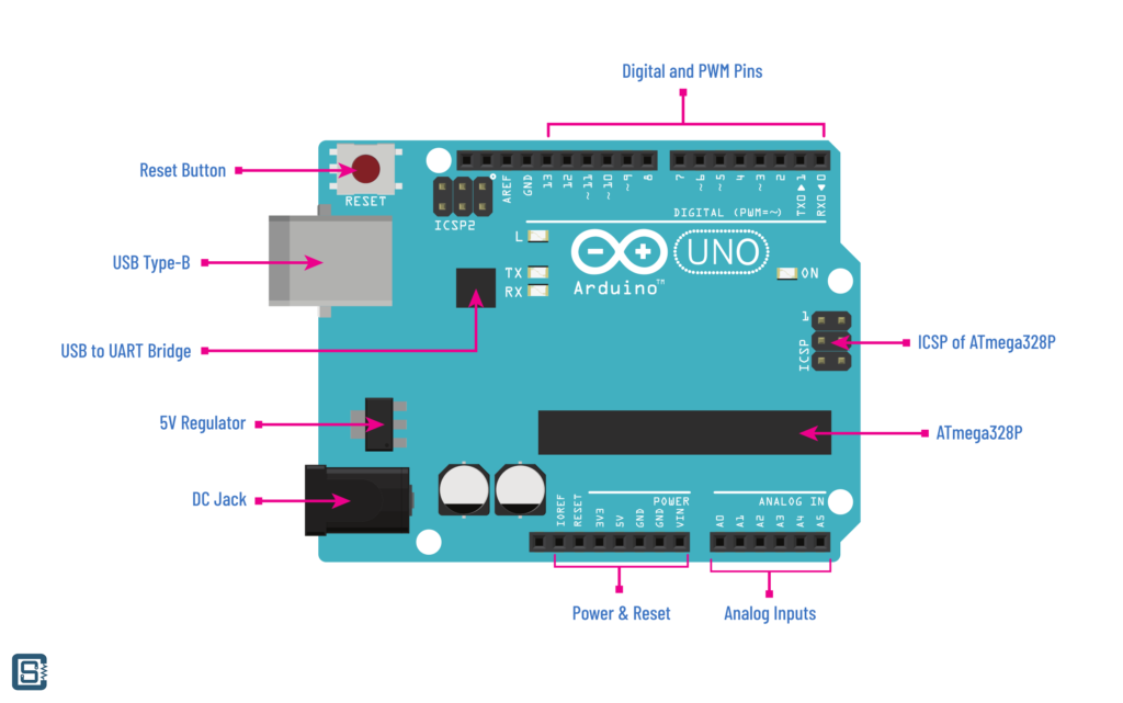
The LEDs labeled as TX and RX are serial communication indicators. By default, digital pins 0 (RXD) and 1 (TXD) are connected to the USB-to-UART bridge which handles the communication between the Uno board and a computer. When there is communication happening between your board and the computer, the TX and RX LEDs will flash. The LED labeled as L is the debug LED connected to digital pin 13.
When the board is connected via USB, the Uno gets a 5V supply directly from the USB. But if USB is not available, you can use the DC barrel jack to supply power. The DC jack can accept any voltage between 7 to 12V. The onboard 5V regulator will convert this voltage range to a fixed 5V for the microcontroller. This power will also be available at the power pin headers. Moreover, the Uno board also produces a 3.3V supply for additional low-voltage peripherals. You can use this supply line for connecting low-voltage sensors and displays. The ON LED will remain on when the board has power.
The RESET button will reset the microcontroller. After a reset, the microcontroller will execute the program from the beginning. The ICSP1 (ATmega328P) and ICSP2 (ATMEGA8U2-MU) are programming headers to be used by an external programmer. ICSP pins can also be used as SPI headers.
Arduino IDE
IDE stands for Integrated Development Environment. High-level code is written in human-readable plain text. So you can use any text editor to write code. You just need to give proper extensions such .c, .h, etc to the files you create. An IDE is a text editor on steroids. It incorporates a lot of features that are not found in conventional text editors such as Notepad. Mainly an IDE can do the following.
- Syntax Highlighting – Depending on what programming language you are using, an IDE can highlight parts of your code in different colors and styles so that you can easily differentiate between words and symbols in your code. This is immensely better than reading all-black code.
- Auto-Indentation – Indentation is a style of adding consistent white spaces to separate blocks of code. Indentation makes it easy to read and browse code. An IDE can put indentations automatically depending on what you are typing, instead of having to hit the spacebar repeatedly.
- Code Completion – IDE can suggest keywords, functions, and other references when you start typing. Some keywords can place the entire code template for you. This reduces the number of keystrokes you have to make.
- Intellisense – IDE can find references in your code and allow browsing through them. Intellisense also helps in code completion.
In addition to these, an IDE can integrate a compiler, programmer, debugger, file explorer, and versioning on a common interface. This means you don’t have to leave your IDE for anything. Arduino code is written with the help of the Arduino IDE.
Download & Install
Arduino offers three IDE options; IDE 1, IDE 2, and Web IDE. You can use any of them to write Arduino code and upload them to Arduino boards. Here, we will explore only IDE 1, because that is the simplest among the three. Download Arduino IDE 1 from below.
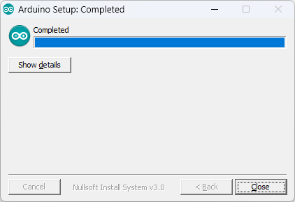
Choose the installer or package that is suitable for your operating system, and install it with default options. We are using Windows 11 and therefore all of our screenshots will be from Windows.
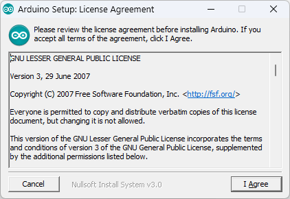
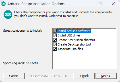
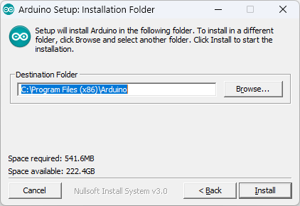
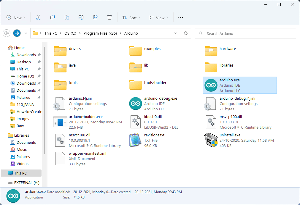
As you can see we have chosen the default location for installation. Arduino IDE installs the AVR toolchain (compiler, programmer, etc.) to this default location. When you install a new version, all contents of this main folder will be deleted. So make sure you don’t add any changes to the contents of the root folder.
Features
A detailed explanation of the interface can be found here on the Arduino website. But we are more interested in two of the main functions; Verify and Upload.
- Verify – Checks the code for errors. If there are errors, they will be highlighted so that you can fix them. If there are no errors, the code will be compiled completely. When a code compiles successfully, that means you are ready to upload it to your board.
- Upload – This compiles and uploads the code to your board. The board should be connected to the computer and the correct port should be selected from the menu.
Example Sketches
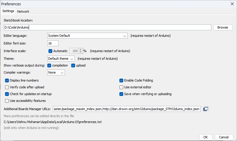
An Arduino program file is called a sketch and has the extension .ino. It is just a text file with a custom extension. Your sketches will be stored in a sketchbook folder. You can change this folder to a new location by opening the preferences at File → Preferences. The Preferences window has many other options such as the font size used for the editor. If you think the font size is too small, try increasing it.
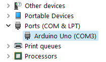
Before you can upload code to your board, you need to connect it to your computer with a USB cable. When the device is detected, a COM port will be created. COM port is simply a serial communication port initialized by the USB-to-UART chip on the Uno board. Through this serial port, we can send or receive data from a computer. In Windows, the COM port will get a name like COM3, COM4, etc. The number is not permanent but can change when you reconnect your device. When you connect multiple serial devices to your computer, each device will get a new COM port number. So make sure you select the correct COM port before uploading the code. To choose the COM port, go to Tools → Port and choose one from the list.
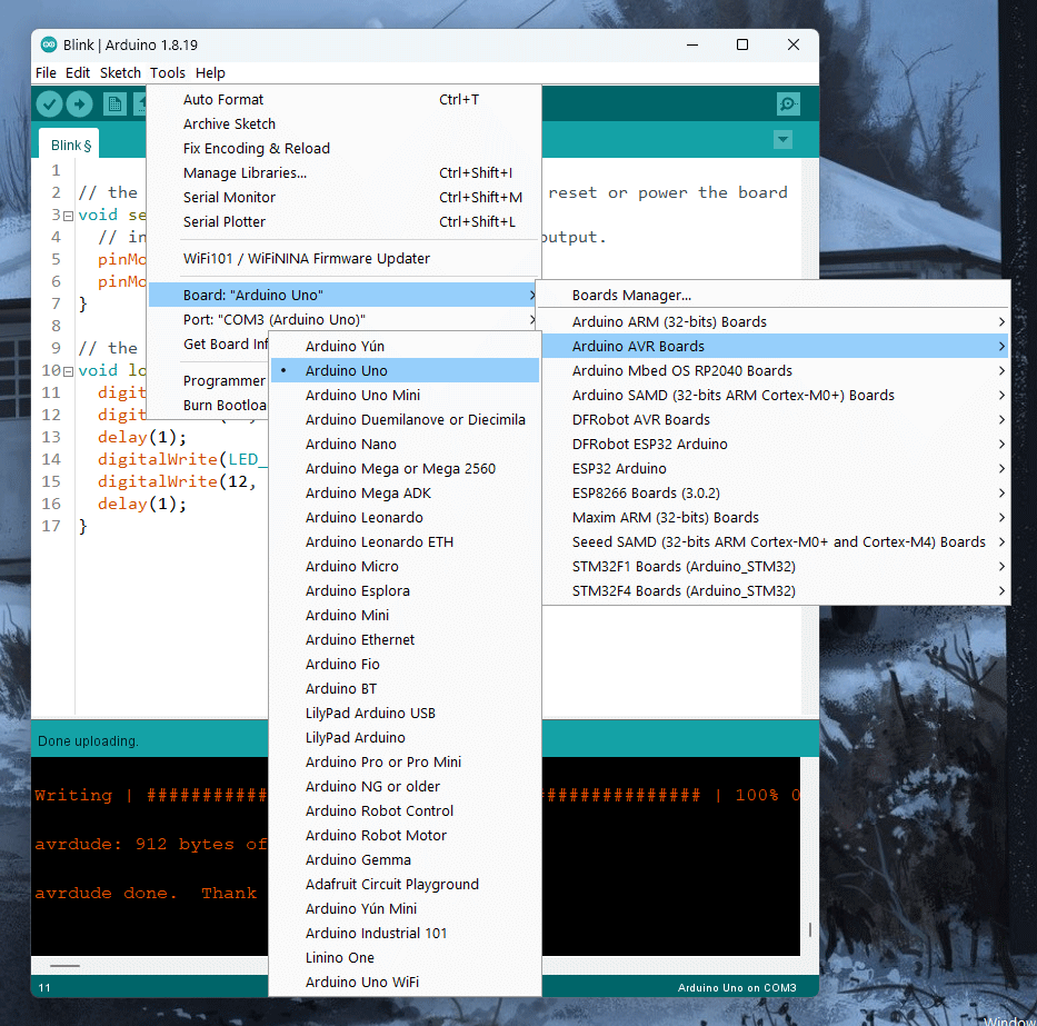
Next, you need to select the board. Since Arduino IDE can support different types of Arduino boards, we need to tell the IDE which board we want to use. Select the board from Tools → Board → Arduino AVR Boards → Arduino Uno. When you select the board and port, a string will appear on the bottom-right corner of the IDE, saying Arduino Uno on COM3, for example. Now you are good to go.
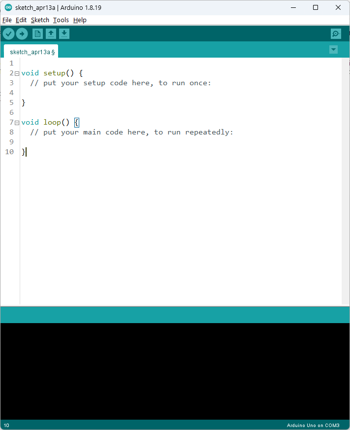
The Arduino IDE will open a blank sketch when you first open it. There will be two functions namely setup() and loop(). These two functions form the bare minimum of Arduino sketch. The setup() function is executed only once when the power is turned on for your board or the reset button is pressed. The setup() function takes care of initializing many of the hardware peripherals. Once everything is initialized, the loop() function will be executed continuously and indefinitely. We will learn the importance of these functions with the help of a few examples.
Blinking Onboard LED
Arduino IDE comes with many prebuilt example sketches to get you started easily. Blinking an LED is a celebrity among them. It is the “Hello World” for hardware. The Blink sketch simply flashes an LED at a rate that you can specify. To open the example sketch go to File → Examples → 01.Basics → Blink. This will open the Blink sketch in a new window.
// the setup function runs once when you press reset or power the board
void setup() {
  // initialize digital pin LED_BUILTIN as an output.
  pinMode (LED_BUILTIN, OUTPUT);
}

// the loop function runs over and over again forever
void loop() {
  digitalWrite (LED_BUILTIN, HIGH);   // turn the LED on (HIGH is the voltage level)
  delay (1000);                       // wait for a second
  digitalWrite (LED_BUILTIN, LOW);    // turn the LED off by making the voltage LOW
  delay (1000);                       // wait for a second
}
Most Arduino boards come with an LED onboard that is connected to one of the GPIO pins of the microcontroller. For Uno, this is a small orange LED connected to digital pin 13 (not the physical pin number). So we are going to blink that LED. The logic for blinking an LED is as follows.
- Turn ON the LED.
- Wait for some time.
- Turn OFF the LED.
- Wait for some time.
- Repeat from line 1.
This will continuously blink the LED at a rate determined by how long you wait after either turning ON or OFF the LED. The logic described in words is called an algorithm.
Let’s examine our code now. The first 23 lines of the sketch are actually a multi-line comment. A multi-line comment starts with /* and ends with */. The purpose of comments is to describe something within your program. They are not part of the actual logic of your program. If you do not use the /* and */ tags when adding a description, then that’s an error and your code won’t compile. Similarly, line sections that start with //are also comments, but not multi-line but single-line comments. Single-line comments do not have an ending tag. In Arduino IDE, comments will be highlighted in gray color. This is an advantage of using syntax highlighting. Normal text editors won’t give you this feature.
The actual code starts at line 26 with void setup() {. This is the start of the function and the opening curly bracket encloses everything that is part of the setup() function. The setup function ends at line 29 where the closing curly bracket is at. The code you write within the brackets is executed only once. Every code line you write is going to be executed sequentially; one after another. That means, for example, line 12 is executed only after executing line 11. This is how we will write all the logic required for our program.
We already know that the pins of a microcontroller can have multiple functions. So in the setup() function, we are going to tell the microcontroller which function we intend to use. For blinking an LED, we need a GPIO function in output mode. To initialize a digital pin as an output, we need to use the pinMode() function. We have to pass two parameters to the function; the pin number and the mode.
pinMode (LED_BUILTIN, OUTPUT);Remember the built-in LED on Uno? LED_BUILTIN is actually a constant number that represents the digital pin 13 to which the LED is connected. If you replace LED_BUILTIN with 13, the code will still work. OUTPUT says we need a digital output (either HIGH or LOW) function on the pin. Since we are only using a single pin, that is all required in the setup() function.
On line 32 is the start of the loop() function and it ends at line 37. Inside the loop() function are four statements. The first is,
digitalWrite (LED_BUILTIN, HIGH);digitalWrite() is a function available for setting the output state of a digital pin. It sets a digital output pin to either HIGH (5V) or LOW (0V). Similar to pinMode() function, digitalWrite() function also needs two parameters; the pin number and the output state. LED_BUILTIN is our output pin and HIGH is our output state. When this line is executed, the LED on the Uno board will turn on.
The next line to be executed is at line 34.
delay (1000);After turning ON the LED, we need to wait for some time as per our algorithm. delay() function asks the microcontroller to wait for a time period before executing the next line. It needs one parameter; the time to wait. Here we specify wait time in milliseconds. Since 1000 ms = 1 s, the microcontroller will wait for 1 second before executing code line 35.
The next line is again a digitalWrite() function but with the second parameter as LOW. This will simply turn off the LED. After turning off the LED, we need to again wait for 1 second as per our algorithm.
digitalWrite (LED_BUILTIN, LOW);
delay (1000);
So what happens after line 36? In the case of setup() function, code after its closing bracket was executed. But in the case of loop() function, there is no more code to execute. But loop() is a special function. When the loop() function reaches the end, it will simply restart. That means, after executing line 37, the program will start executing line 32 again. This will continue forever. And that’s what our algorithm also says. We need to repeat our instructions repeatedly to blink the LED continuously. We will see this in action after uploading our code.
To upload, you must have your Arduino board connected to the computer and the port selected at Tools → Port. Then simply click the Upload button on the top-left. The Arduino IDE will start to compile the program. If it finds any errors, it will stop the compilation process and report any errors. But since we are using an example sketch, there won’t be any errors. The compiler turns your high-level program into a binary form understood by the microcontroller. The binary file will be then uploaded to the Uno board and a Done uploading. message will appear at the bottom of the IDE. You will now see the orange LED on your Uno board blinking.
If you change the time periods passed to delay() functions, you can change the ON or OFF time of the LED. Play around with the values to see how fast you can blink the LED. You can also blink the LED in different patterns by adding more digitalWrite() and delay() statements. For example, the following program blinks the LED in a pattern of three blinks.
// the setup function runs once when you press reset or power the board
void setup() {
  // initialize digital pin LED_BUILTIN as an output.
  pinMode (LED_BUILTIN, OUTPUT);
}

// the loop function runs over and over again forever
void loop() {
  digitalWrite (LED_BUILTIN, HIGH);
  delay (100);
  digitalWrite (LED_BUILTIN, LOW);
  delay (100);
  digitalWrite (LED_BUILTIN, HIGH);
  delay (100);
  digitalWrite (LED_BUILTIN, LOW);
  delay (100);
  digitalWrite (LED_BUILTIN, HIGH);
  delay (100);
  digitalWrite (LED_BUILTIN, LOW);
  delay (1000);
}
Blinking External LED
So far we have been blinking on the onboard LED. Now let’s blink an external LED connected to the Arduino Uno. For this experiment you additionally need,
- 1 x 5 mm LED of any color
- 1 x Solderless Breadboard
- 1 x 220 Ohms through-hole resistor
- 1 x Male-to-male jumper wires
Connect the components as shown in the following wiring diagram.
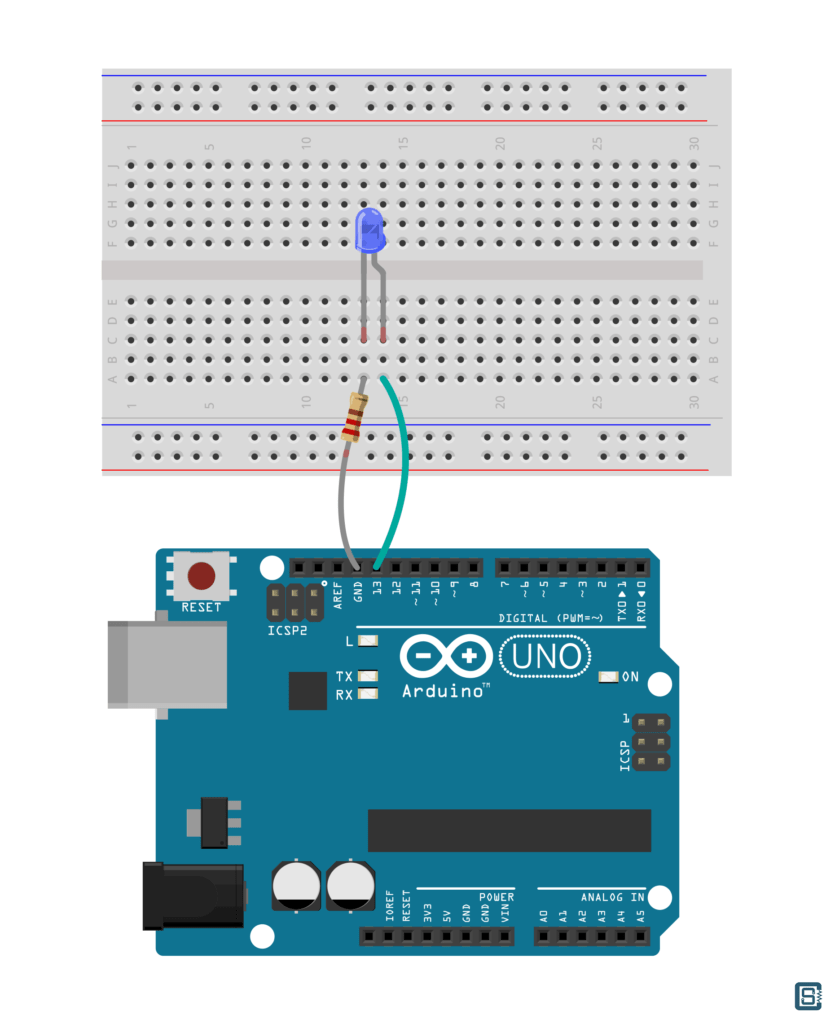
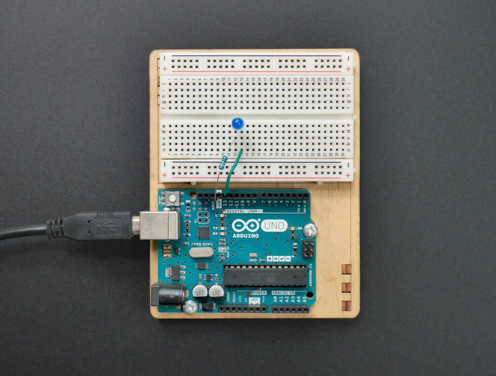
The Anode (positive) pin of the LED is connected to the digital pin 13 of Uno and the Cathode (negative) pin is connected to GND (Ground) through a 220 Ohms resistor. When you upload the Blink sketch, both the onboard and the external LEDs will blink together. If you want the LEDs to blink separately, you can add a new digital pin to your code as shown below.
// the setup function runs once when you press reset or power the board
void setup() {
  // initialize digital pin LED_BUILTIN as an output.
  pinMode (LED_BUILTIN, OUTPUT);
  pinMode (12, OUTPUT);
}

// the loop function runs over and over again forever
void loop() {
  digitalWrite (LED_BUILTIN, HIGH);
  digitalWrite (12, LOW);
  delay (500);
  digitalWrite (LED_BUILTIN, LOW);
  digitalWrite (12, HIGH);
  delay (500);
}
As you can see, we have defined digital pin 12 as an output. This way, we can separately control the digital pin 12. Now upload the code and change the external LED’s anode connection to pin 12 of Uno. Both onboard and external LEDs will be blinking alternatively.
Observe the following two lines,
digitalWrite (LED_BUILTIN, HIGH);
digitalWrite (12, LOW);
We have two separate lines for setting the output of the digital pins. You might wonder if there is any delay in turning off one LED and turning on the other LED. There will be a really small delay in the range of a few milliseconds if not microseconds. But you won’t be able to see it. You will see the external LED turning on at the same time the onboard LED turns off. To see why you can’t see such small delays, try changing the delay value to 1 millisecond. You will see both LEDs being ON at the same time, even though your code has instructions to turn off the LEDs.
That is all for this tutorial. We hope you find it informative as a beginner. We have tried our best to explain every term you might find new. But there can be a lot of things that are still confusing to you. But getting confused is a good thing. That’s how brains learn. Try searching the terms you did not understand and reading the explanations you can find. Over time you will start to fill the gaps and acquire a complete picture of how microcontrollers work and the best ways to program them. We will be publishing more tutorials like these in the coming weeks. If you want to learn about using Microsoft Visual Studio Code (VS Code) for Arduino development, check out the following tutorial from us.
How to Use VS Code for Creating and Uploading Arduino Sketches
Links
- Download Arduino IDE
- Arduino IDE Overview
- Arduino Uno – Hardware Reference
- Arduino Uno R3 Schematic PDF
- Arduino Uno – Datasheet PDF
- ATmega328P – Pinout Diagram PDF
- ATmega328P – Datasheet Complete PDF
- Wiring – Official Site
- Buy Official Arduino Uno – Robu
- Buy Arduino Starter Kit – Robu
- Arduino Education
- Arduino Pro
- Arduino IoT Cloud
Short Link
- Short URL to this page – https://circuitstate.com/getsard


