What is CAN Bus & How to use CAN Interface with ESP32 and Arduino
Learn the basics of CAN bus interface and learn how to make two ESP32 boards communicate through CAN bus using Arduino and with the help of TJA1051 CAN transceivers (CJMCU-1051).

CAN Bus or Controller Area Network is a communication interface standard widely used in the automotive industry. As vehicles have become more of technology on wheels rather than just mechanical devices, the use of electronic sensors, actuators, and interfaces became vital for their functioning. Since different electronic systems may be placed in different places on a vehicle, there should be some way to make them communicate with each other so that one system knows what is happening to some other system. Mainly the ECU (Electronic Control Unit) has to get real-time data from different sensors so that it can adjust whatever output parameters in response to user input such as pressing the throttle. Manufacturers quickly realized that they needed some standard communication interface that can carry information from one system to another reliably and fast enough. This interface has to be highly robust since the working environment of a vehicle can be unpredictable and harsh. Noise, interference, voltage surges, high temperature, low temperature, vibration, and all can work against the critical electronic systems of a vehicle and put the passengers in danger. This interface has to be standardized so that the huge industry of aftermarket products can continue to exist and manufacturers of sensors and other products can save time and cost on product development.
CAN bus was developed by Robert Bosch GmbH and it is now an ISO (International Standards Organization) approved communication interface ISO 11898 with multiple specifications released over the years. The ESP32 microcontroller from Espressif also has an integrated CAN bus controller. Since it is highly likely that you have an ESP32 board with you, we thought we would use ESP32 for our first CAN bus tutorial. In this post, we will learn the basics of CAN interface, how to configure the integrated CAN bus controller of the ESP32, how to interface the TJA1051 external CAN transceiver with ESP32 and how to make two ESP32 boards communicate via the CAN interface.
Need CAN Bus integration in your project?
CIRCUITSTATE can develop and deploy CAN Bus communication networks for your next project. Take advantage of the robust communication network for automotive and industrial applications. Contact us today to share your requirements.
CAN Bus
Controller Area Network (CAN) is a standard defining the physical description (PHY) and the Data Link Layer of a differential bus communication interface. CAN is a de-facto communication interface extensively used in automotive and industrial applications. CAN uses a bus topology for its network. Multiple devices can connect to the same shared bus. A similar interface you can think of is the I2C bus. But unlike I2C, a CAN bus uses differential signals, has faster data rates, and can communicate reliably over longer distances. CAN bus can extend up to 1000 meters with suitable cabling but with reduced data rate with increased lengths.
Signaling
A CAN bus consists of two signal lines CAN High (CAN-H) and CAN Low (CAN-L) with an additional GND line for common reference. Each device connected to a CAN bus is called a node. Both ends of the bus should be terminated with 120 Ohms resistors (Rterm). These resistors help to keep the bus in a predictable state and reduce signal reflections. Both signal lines are differential in nature. That means, they both carry the same information at the same time but in opposite polarities. Differential signaling is better conveyed through an illustration.
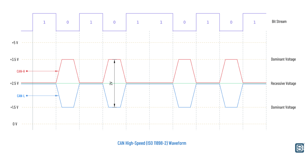
In the illustration above, we are using 0V as the GND potential and 5V as the maximum positive potential. In an idle condition, both CAN-H and CAN-L stay around at half of the maximum positive potential, which is 2.5V here. The two signal lines can together indicate two other states called Dominant which indicates a digital 0 and Recessive which indicates a digital 1. A dominant state is activated when the CAN-H line is driven to a higher voltage level and the CAN-L line to a lower voltage level from the idle 2.5V. A recessive state is activated by driving CAN-H to a lower potential and CAN-L to a higher potential relative to their idle levels. The table below summarizes this.
| State | CAN-H | CAN-L | Difference | Bit |
|---|---|---|---|---|
| Idle | 1/2 | 1/2 | 0 | 1 |
| Dominant | HIGH | LOW | CAN-H > CAN-L | 0 |
| Recessive | LOW | HIGH | CAN-H ≤ CAN-L | 1 |
That’s how we encode digital information on a differential line. The difference is always taken as (CAN-H – CAN-L). The reason why dominant is regarded as 0 is that the CAN bus is a shared and asynchronous line. Any devices connected to the CAN bus may transmit data at any time by driving the common bus lines. There are no clock signals or any other signals that select (like the chip-select for SPI) which device to transmit first. So when two devices try to transmit together, the device that drives the line to the dominant state wins access to the bus. This process is called arbitration. As we will see further, this arbitration mechanism helps in prioritizing communication over the shared CAN bus which is a very important feature.
The exact voltages that represent the HIGH and LOW states on the signal lines can depend on the type of interface standard used. ISO 11898-2, also called High-Speed CAN (bit speeds up to 1 Mbit/s on CAN, 5 Mbit/s on CAN-FD), uses a linear bus terminated at each end with 120 Ω resistors. A dominant state is asserted by driving CAN-H to 3.5V and CAN-L to 1.5V with a difference voltage of 2V. For the recessive state, both lines remain undriven and the termination resistors bring the lines to the idle level of 2.5V with a difference of 0V. Nodes will consider any difference of less than or equal to 0.5V as recessive. Let’s summarize this in a table.
| State | CAN-H | CAN-L | Difference (CAN-H – CAN-L) | Bit |
|---|---|---|---|---|
| Dominant | 3.5V | 1.5V | +2V | 0 |
| Recessive | 2.5V | 2.5V | 0V (anything <0.5V) | 1 |
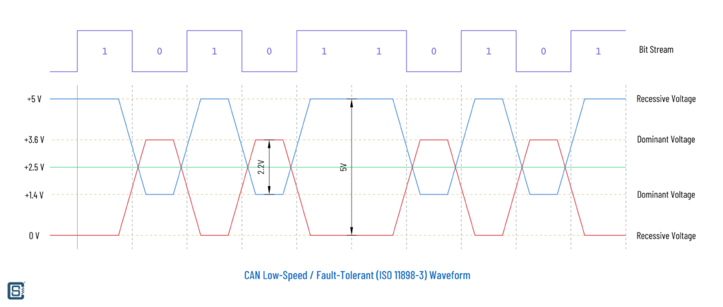
But there is another standard for CAN bus called ISO 11898-3 which is also known as Fault-Tolerant CAN or Low-Speed CAN. The maximum data rate is limited to 125 kbps here but the network topology can be a star, bus, or a mix of both. Also, instead of using just two termination resistors, nodes will use fractional values to keep the overall impedance of the network at around 100 Ω. CAN-H will be pulled up and the CAN-L line will be pulled down by default. Low-Speed CAN uses larger voltage swings to improve signal robustness as listed in the table below. From the waveform, you can tell that High-Speed CAN signals are not compatible with Low-Speed CAN. So when you want to use one over the other, you need to change the CAN transceiver, but the CAN controller can be the same. You are more likely to encounter High-Speed CAN and that’s what we are going to use for the demonstration as well.
| State | CAN-H | CAN-L | Difference (CAN-H – CAN-L) | Bit |
|---|---|---|---|---|
| Dominant | +3.6V | +1.4V | +2.2V | 0 |
| Recessive | 0V | 5V | -5V | 1 |
As we have seen, it is the difference between the signal lines that we use to encode digital 1 or 0, instead of their individual voltages. The advantage of using this type of differential signaling is that it helps to remove Common Mode (CM) noise effectively. CM noise is a type of interference that alters the voltages or currents carried by signal lines in the same way. CAN standards specify the maximum common mode voltages that are allowed on the lines but do not specify how to maintain them.
Bit Timing
Since there is no dedicated clock line used in the CAN bus, all nodes must agree on using the same nominal bit rate in order to communicate through the same bus. But since each node will have separate oscillators of different tolerances for generating their base clock signals, we can not expect all of the frequencies to be the same. This is where synchronization comes into play. The nodes can recover the clock from the transmitted signals themselves and adjust it dynamically. All CAN nodes must be able to do this. A hard synchronization occurs on the first recessive to dominant transition (1 → 0) after a period of bus idle (the start bit). Resynchronization occurs on every recessive to dominant transition during the frame. The CAN controller expects the transition to occur at a multiple of the nominal bit time. If the transition does not occur at the exact time the controller expects it, the controller adjusts the nominal bit time accordingly.
To make this process easier, a single nominal bit time is divided into a number of equal time slices called Quanta (Tq). These quanta are then assigned to four phases called synchronization, propagation, phase segment 1, and phase segment 2. The number of quanta is usually programmable, and the number of quanta assigned to each segment can be varied depending on bit rate and network conditions.
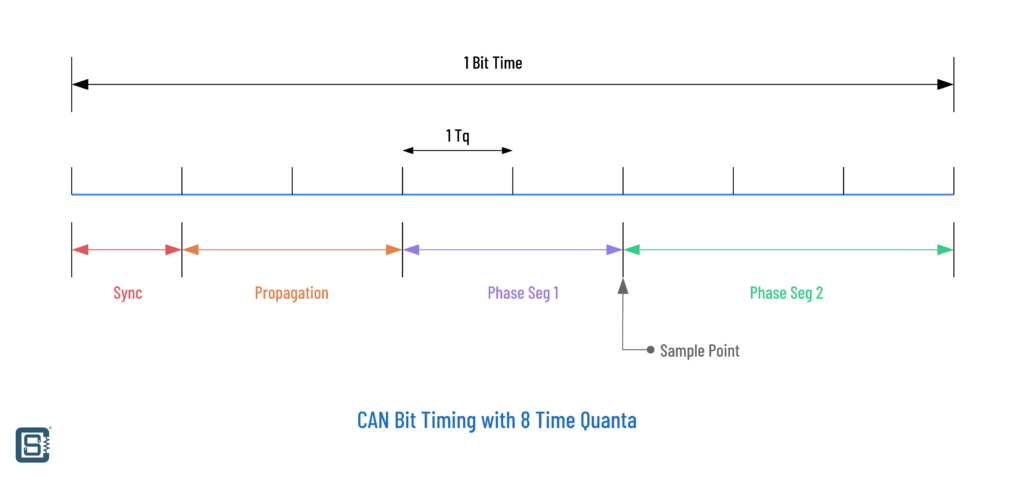
A transition that occurs before or after it is expected causes the controller to calculate the time difference and lengthen phase segment 1 or shorten phase segment 2 by this time. This effectively adjusts the timing of the receiver to the transmitter to synchronize them. This resynchronization process is done continuously at every recessive to dominant transition to ensure the transmitter and receiver stay in sync. Between the phase segments 1 and 2 is the Sample Point at which a CAN transceiver actually reads the logical state of the bit. Continuously resynchronizing reduces errors induced by noise, and allows a receiving node that was synchronized to a node that lost arbitration to resynchronize to the node that won arbitration.
Usually, when you have to specify the bit rate of the CAN bus, you either specify the nominal bit rate and let the CAN controller take care of managing the synchronization process, or specify the exact values for all four segments of the synchronization.
Frame Format
CAN data transmission consists of sending and receiving bits. Any node can initiate a transmission if the bus is free. The process of gaining bus access is called arbitration. If two nodes send a 0 at the same time, the resultant bit will be 0. Similarly for bit 1. But if a node sends 0 but another one sends a 1, the resultant bit will always be 0.
A node can only transmit if it wins the arbitration and in order to win the arbitration it must be using a higher-priority message ID than other nodes. All nodes on the CAN bus can listen to all other transmissions as well as their own. For example, consider there are two nodes, A with address 100 and B with address 110. Suppose both nodes are sending their MSBs first. When both A and B assert their first bit (1), both A and B see a successful assertion because they both sent 1 and saw 1 on the bus. Then they send the next bit. But this time, A asserts 0 and sees a 0. But B will try to assert 1 but will not see a 1 on the bus. Thus B knows that it has lost the arbitration and A with a higher priority ID has won the arbitration and should pause until A’s transmission is complete. Node A doesn’t know if B is transmitting at all. It just wins the arbitration and continues to transmit without any delays or contention. Node B will retry its transmission some period after A has completed its. All nodes on the bus follow this procedure and therefore contentions are easily avoided. Note that a node with the most number of 0s at the start of the frame, or the lowest ID always wins the arbitration.
Wikipedia has an example of this. Consider an 11-bit ID CAN network, with two nodes with IDs of 15 (binary 00000001111) and 16 (binary 00000010000). If these two nodes transmit at the same time, each will first transmit the start bit and then transmit the first six zeros of their ID with no arbitration decision being made.
| Start Bit | ID Bits | Rest of the frame | ||||||||||||
| 10 | 9 | 8 | 7 | 6 | 5 | 4 | 3 | 2 | 1 | 0 | ||||
|---|---|---|---|---|---|---|---|---|---|---|---|---|---|---|
| Node 15 | 0 | 0 | 0 | 0 | 0 | 0 | 0 | 0 | 1 | 1 | 1 | 1 | ||
| Node 16 | 0 | 0 | 0 | 0 | 0 | 0 | 0 | 1 | Stopped Transmission | |||||
| CAN data | 0 | 0 | 0 | 0 | 0 | 0 | 0 | 0 | 1 | 1 | 1 | 1 | ||
When the 7th ID bit is transmitted, the node with the ID of 16 transmits a 1 (recessive) for its ID, and the node with the ID of 15 transmits a 0 (dominant) for its ID. When this happens, the node with the ID of 16 knows it transmitted a 1, but sees a 0 and realizes that there is a collision and it lost arbitration. Node 16 stops transmitting which allows the node with ID of 15 to continue its transmission without any loss of data. The node with the lowest ID will always win the arbitration, and therefore has the highest priority.
But what if two nodes try to transmit with the same IDs? Well, first all nodes should have a unique ID whenever possible. If that’s not possible, CAN supports error detection and automatic retry mechanisms. But let’s first check what a normal data frame for CAN looks like. There are two types of CAN message frames.
- Messages with 11-bit IDs defined by CAN 2.0A. This is called a Standard Frame.
- Messages with 29-bit IDs defined by CAN 2.0B. This is called an Extended Frame.
Since the IDs are used for unique messages and nodes, with a longer ID we can have more number of unique messages and devices with more priority levels. The standard frame allows a maximum of 211 = 2048 IDs and the extended frame allows 229 = 536870912 IDs. That’s a huge difference. Cool thing is that both standard and extended frames can be used on the same bus. But as we have seen before, the lower IDs with more numbers of 0s on the MSB side will always win the arbitration. So standard frames get priority over extended frames.
But wait, what are CAN 2.0A and CAN2.0B? The original CAN 2.0 specification has two sections the describe two types of frame formats – standard (A) and extended (B). So CAN 2.0A and 2.0B just indicate the frame formats they support. Whenever possible, try to use the frame format names instead of 2.0A and 2.0B.
Standard Frame
Below is a complete standard CAN frame with correct CRC, stuff bits, and inter-frame spacing. You can see the actual CAN bit stream and CAN-H and CAN-L signal levels. It also shows CAN RX which we will talk about later. For now, just consider it represents the CAN bit stream. It it hasn’t become obvious yet, CAN bus always transmits MSBs first.
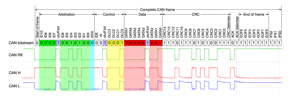
The contents of the frame can be broken down as below.
| Field name | Length (bits) | Purpose |
|---|---|---|
| Start-of-Frame (SOF) | 1 | Denotes the start of frame transmission |
| Identifier | 11 | A (unique) identifier which also represents the message priority |
| Stuff Bit | 1 | A bit of the opposite polarity to maintain synchronization |
| Remote Transmission Request (RTR) | 1 | Must be dominant (0) for data frames and recessive (1) for remote request frames |
| Identifier Extension Bit (IDE) | 1 | Must be dominant (0) for base frame format with 11-bit identifiers |
| Reserved Bit (r0) | 1 | Reserved bit. Must be dominant (0), but accepted as either dominant or recessive. |
| Data Length Code (DLC) | 4 | Number of bytes of data (0–8 bytes) |
| Data Field | 0–64 (0-8 bytes) | Data to be transmitted (length in bytes dictated by DLC field) |
| CRC | 15 | Cyclic Redundancy Check |
| CRC Delimiter | 1 | Must be recessive (1) |
| ACK Slot | 1 | Transmitter sends recessive (1) and any receiver can assert a dominant (0) |
| ACK Delimiter | 1 | Must be recessive (1) |
| End-of-Frame (EOF) | 7 | Must be recessive (1) |
| Inter-Frame Spacing (IFS) | 3 | Must be recessive (1) |

That’s too many items. Let’s explain each of them.
Start of Frame (SOF)
SOF is simply a transition from an idle state to a dominant state. Every node connected to the CAN bus will recognize this transition as the start of a new frame and adjust their timings accordingly (synchronization).
Identifier
This is part of the value that is used to win the arbitration. In standard frames, this will be an 11-bit value. For extended this will be 29-bit, but encoded in a different way which we will see further. The ID is transmitted MSB first.
Stuff Bit
To maintain synchronization, CAN bus requires that an opposite polarity bit is stuffed after every 5 consecutive bits of the same polarity, in a process called bit stuffing. So if we send 00000 consecutively, then the next bit should be a 1 regardless of what data bit comes next. If we send the bits 11111 consecutively, then we must send a 0 next. CAN controllers are smart enough to recognize these bits and remove them from the actual data you get. So all data remain the same regardless of the number or positions of the stuff bits. This process is called bit destuffing.

Remote Transmission Request (RTR)
Generally, nodes with data will send their data autonomously at regular intervals. Other nodes can poll the CAN bus for the data they need. But it is also possible to send a request for data through the CAN bus. This is accomplished by the RTR bit. If a node wants data from another node on the bus, it can simply set the RTR bit to 1. A listening node with the corresponding data can respond with the data requested if it decides to. For normal broadcasted data frames, the RTR bit will be 0. If a data frame and remote frame with the same ID are transmitted at the same time, the data frame will win the arbitration due to the dominant 0 of RTR. An RTR frame doesn’t need to contain any data in the payload section and therefore the DLC can be 0.
Identifier Extension Bit (IDE)
This single-bit field identifies which type of frame it is. If the value is 0, then the frame is a standard type. If it is 1, then the frame is an extended one.
Reserved Bit (r0)
This is a bit field reserved for future use. This should be 0.
Data Length Code (DLC)
This is a 4-bit field indicating the number of data bytes the frame is carrying. The number of bytes can be from 0 to 8. That means, if you have more than 8 bytes of data to send, then you must split it into multiple frames. The 0 length data is usually used along with RTR frames, since we are only requesting the data. Another thing to note is that even though the 4-bit field is just for indicating the length, some systems allow us to set a value of more than 8, which is from 9 to 15. Even in that case, the number of bytes will remain at 8 but you can send an extra 8 values with your frames. Nice hack!
Data Field
This is our actual data ranging from 0 to 8 bytes. The number of bytes is determined by the value of DLC. Data is always sent with MSB first just like all other fields.
CRC
Cyclic Redundancy Check (CRC) is a type of error detection mechanism used in digital data links. CRC can only detect errors and cannot fix those errors. Usually, some kind of hashing function is used to generate a unique value for the data carried by a payload. Also, in its most simple implementation, CRC will be calculated by taking the arithmetic sum of the bytes of the payload and trimming it to some fixed length. A receiver will use the same CRC algorithm that was used by the transmitter. CAN uses the BCH Code for generating CRC. If the CRC calculated by the receiver doesn’t match the CRC read from the packet, the receiver can request a retransmission if requried, or just ignore the bad packet.
CRC Delimiter
This indicates where the CRC data ends. This must be 1 always.
ACK Slot
ACK stands for Acknowledgement. When a transmitter node sends data through a CAN bus, all other nodes can read the transmission. If the transmission was error-free, any one of the nodes can use the ACK slot to indicate to the transmitter that the last transmission was received without any errors. So the ACK slot is sent as 1 by the transmitter and any node can assert a 0 to indicate successful reception. Since the asserted value is a dominant 0, it wouldn’t cause any issues even if multiple receiving nodes asserted 0 at the same time. At the transmitter side, it can either check the ACK slot for a positive confirmation (ACK is on) or ignore that value (ACK is off).
ACK Delimiter
This is a 1-bit field that delimits the ACK slot.
End-of-Frame (EOF)
This is a 7-bit field indicating the end of a single frame. It must be all recessive. Unlike the previous fields, bit stuffing is not added for EOF or the IFS followed by it.
Inter-Frame Spacing (IFS)
As the name suggests IFS is a delay intentionally added between data frames or remote frames. IFS should consist of at least 3 consecutive recessive bits. But IFS is not added for Overload frames or Error frames as we will see later. Bit stuffing also doesn’t apply to IFS.
Extended Frame
Extended frame uses 29-bit identifiers instead of 11-bit ones. But the 29-bits do not simply replace the 11-bits of the standard frame. If that was the case, standard frames and extended frames would lose compatibility. So instead, the 29-bit ID is split into two parts, Base ID (11-bits) and Extended ID (18-bits) as shown in the table below.

Since many fields are similar to the standard frame format, only the new or different fields are explained below.
| Field name | Length (bits) | Purpose |
|---|---|---|
| Start-of-Frame (SOF) | 1 | Denotes the start of frame transmission |
| Base ID | 11 | The first 11 MSBs of the 29-bit ID |
| Substitute Remote Request (SRR) | 1 | Must be recessive (1) |
| Identifier Extension Bit (IDE) | 1 | Must be recessive (1) for extended frame format with 29-bit identifiers |
| Extended ID | 18 | The remaining 18 bits of the 29-bit ID |
| Remote Transmission Request (RTR) | 1 | Must be dominant (0) for data frames and recessive (1) for remote request frames |
| Reserved bits (r1, r0) | 2 | Reserved bits. Must be dominant (0), but accepted as either dominant or recessive. |
| Data Length Code (DLC) | 4 | Number of bytes of data (0–8 bytes) |
| Data Field | 0–64 (0-8 bytes) | Data to be transmitted (length in bytes dictated by DLC field) |
| CRC | 15 | Cyclic Redundancy Check |
| CRC Delimiter | 1 | Must be recessive (1) |
| ACK Slot | 1 | Transmitter sends recessive (1) and any receiver can assert a dominant (0) |
| ACK Delimiter | 1 | Must be recessive (1) |
| End-of-Frame (EOF) | 7 | Must be recessive (1) |
| Inter-Frame Spacing (IFS) | 3 | Must be recessive (1) |
Base ID
Base ID is the first 11-bit MSB of the 29-bit extended ID ranging from ID28 to ID18. The Base ID determines the base priority of the extended frame. For example, if two nodes try to transmit simultaneously with the same ID, but one with a standard frame and one with an extended frame, the node with the extended frame will win the arbitration since its MSBs are all 0s.
Substitute Remote Request (SRR)
As the name suggests, SRR replaces the RTR (Remote Transmission Request) field with a recessive 1.
Identifier Extension Bit (IDE)
Since we have an extended frame format, this field should be a recessive 1.
Extended ID
Extended ID is the remaining 18 bits of the extended ID ranging from ID17 to ID0.
| Base ID | Extended ID | ||||||||||||||||||||||||||||
| 11-Bit ID | 10 | 9 | 8 | 7 | 6 | 5 | 4 | 3 | 2 | 1 | 0 | ||||||||||||||||||
| 29-Bit ID | 28 | 27 | 26 | 25 | 24 | 23 | 22 | 21 | 20 | 19 | 18 | 17 | 16 | 15 | 14 | 13 | 12 | 11 | 10 | 9 | 8 | 7 | 6 | 5 | 4 | 3 | 2 | 1 | 0 |
Remote Transmission Request (RTR)
The RTR has moved its place but its function remains the same.
Reserved bits (r1, r0)
There are two reserved bits that should be always dominant 0.
Error Frames
Part of what gives CAN bus its robustness is the detection of errors and the automatic recovery from them. As we have seen earlier, every transmitting node will monitor its own transmissions. During the arbitration phase, if a node doesn’t see the bit it is transmitting, the node will quickly stop transmission to allow the other higher-priority message to go through. But if a node wins the arbitration, it continues to transmit the other data fields. But errors can occur during normal data transmission phases also. These are errors are broadcasted as error frames over the CAN bus. There are two types of error frames – Active Error Frame and Passive Error Frame.
Active Error Frame
We know that all transmitting nodes will be able to see their own transmissions. So if a node is transmitting a 1 and sees a 0 instead, it is called a Bit Error. Similarly, if any fixed fields, such as SOF, EOF, etc. have error bits in them, it is called a Form Error. As soon as the node detects such an error, it will abort the ongoing transmission and then broadcasts an Error Frame consisting of an Active Error Flag (AEF), followed by an Error Flag Delimiter (EFD). The AEF consists of at least 6 dominant bits and goes up to 12 bits in some cases. The EFD size is always 8 recessive bits which are not actively transmitted but conveyed through an idle state. The error frame containing the AEF can be called an Active Error Frame.

We already know that a CAN node has to do bit stuffing for every consecutive same polarity bits it is sending. When a node detects and sends an error frame, it doesn’t do bit stuffing on the error frames. Not doing bit stuffing is an error called Bit Stuffing Error (BSE), which is usually detected by receivers. So all the receivers who were listening to the erroneous transmission will also send their own AEF. So the final error frame will be actually a superposition of error flags from different nodes. The error flag sent by the transmitting (discovering) node can be called a Primary AEF and the subsequent error flags sent by other nodes can be called a Secondary AEF for convenience.
If all nodes detect a bit error at the same time, they all send AEF (6 dominant bits). Since AEF consists of only dominant 0s, the superimposed or overlapped result will be still 6 dominant bits. After the AEF, there will be an EFD of 8 recessive bits. This is illustrated below.

If a bit error is only detected by a transmitting node, it will immediately transmit the primary AEF and wait for the EFD. But all other nodes will detect a BSE as soon as the primary AEF is ended (after 5 consecutive bits), and will transmit the secondary AEF. This means there are going to be 12 consecutive dominant bits indicating the error frame. It will be followed by the EFD consisting of 8 recessive bits. This is illustrated below.
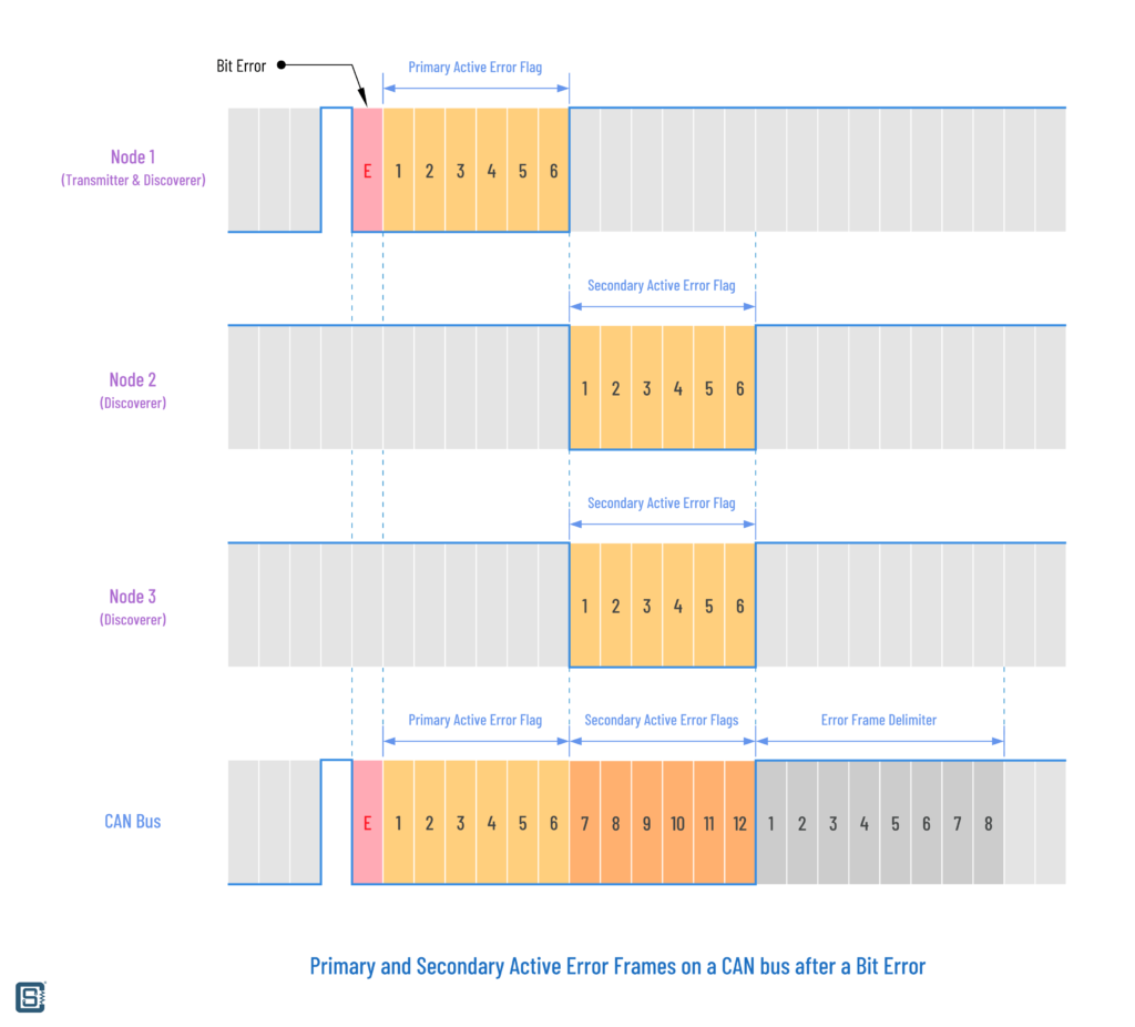
Similarly, the overlapping of different AEF will produce a maximum of 12 dominant bits, and then followed by an EFD. After the EFD, the node that could not finish its transmission can now retry the transmission. In addition to detecting and broadcasting error frames, nodes can enter into different error states called Error Active, Error Passive, and Bus Off. Entering and exiting these states is determined by two error counters found in every node – Transmit Error Counter (TEC) and Receive Error Counter (REC).
- When TEC and REC are less than 128, the node is said to be in an Error Active state. This is the normal working mode. In this state, a node will send an Active Error frame whenever it detects an error on the bus.
- When TEC or REC is greater than 127 and less than 255, the device is said to be in an Error Passive state. The node can still transmit data but it can only send Passive Error frames in response to errors on the bus. Additionally, the CAN node now has to wait for an extra 8 bits (called Suspend Transmission Time) in addition to the 3-bit IFS before it can resume data transmission (to allow other CAN nodes to take control of the bus).
- When TEC is greater than 255, then the node enters into a Bus Off state. In this state, a node can not transmit data or error frames.
Passive Error Frame
A Passive Error Frame is an error frame that contains the Passive Error Flag (PEF). If a CAN node has moved from its default active state to a passive state, it will only be able to raise PEF. A PEF consists of 6 recessive bits. PEF raised by transmitting and receiving nodes has different effects on the bus. If a transmitter is in an Error Passive state, it will send out the PEF. This will be seen by all receiving nodes as BSE and they raise AEF immediately. This is illustrated below.

But if it is a receiver that is Error Passive state, it can still send the PEF. But since PEF are all recessive, they can not interfere with a transmission from a node that is in an active state. This is illustrated below.
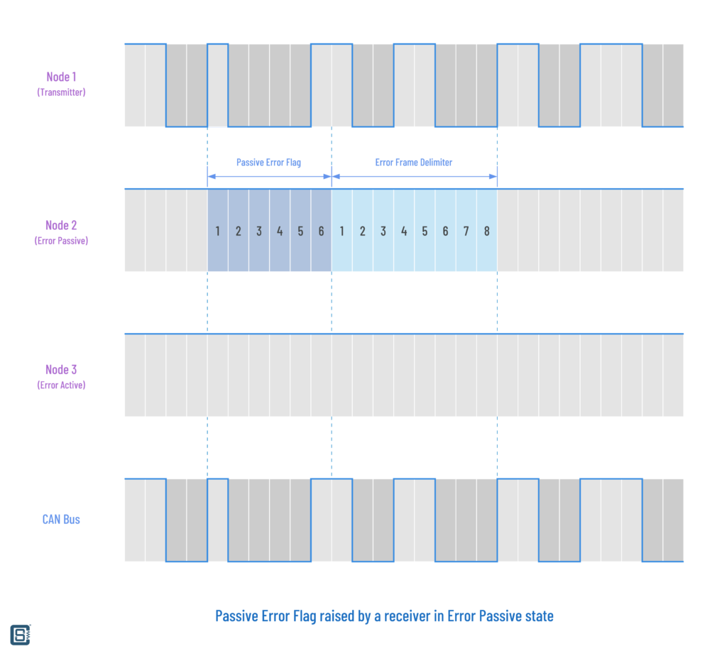
But how do we increment or decrement the TEC and REC counters? How does a CAN node recover from its error states? TEC and REC are incremented and decremented in different ways as listed below.
| Increment / Decrement | Event |
|---|---|
| TEC + 8 | Transmitter raises primary Active Error Flag |
| REC + 8 | Receiver raises primary Active Error Flag |
| REC + 1 | Receiver raises secondary Active Error Flag |
| TEC – 1 | Transmitter successfully sends a message |
| REC – 1 | Receiver successfully receives a message |
The list only shows the basic concept of incrementing and decrementing the error counters. There are a few more cases and exceptions listed on the CAN specification document. But there are a few more things that are useful in knowing. Just like a node enters different states based on the value of the counters, the nodes can also return to their previous working modes when the counter values get decreased.
- A node in the Error Passive state can return to the Error Active (normal) state when both TEC and REC are less than or equal to 127.
- A node in the Bus Off state can become Error Active again if both TEC and REC become 0 after detecting 128 occurrences of 11 consecutive recessive bits on the bus. That means a node returns to normal operation after a period of bus idle.
Finally, let’s summarize the type of errors we will detect on a CAN bus. There are a couple of other types in addition to the ones we have discussed.
- Bit Error – A single-bit error when a transmitter sees a different bit than it is sending. This is only seen by the transmitter.
- Bit Stuffing Error – The violation of the bit stuffing rule. Seen by all nodes.
- Form Error – This happens when fixed bit fields are received differently than they should be, such as SOF, EOF, delimiters, etc.
- ACK Error – This happens when no receiving nodes acknowledge the reception of the message without any errors, during the ACK slot.
- CRC Error – Every receiving node calculates the CRC of the received message. If the calculated CRC doesn’t match what is transmitted by the transmitting node, the CRC Error is raised.
As per the official specification, an error counter value of 96 or greater indicates severe issues with a CAN bus. So it would be better to identify these situations earlier. Also, if there is only one active node on a bus during startup and it tries to send a message, it will not receive any ACK back. So it will cause the node to raise an error and retry the transmission. The node can be in Error Passive state but it will never go to Bus Off state. To learn more about CAN errors and get actual data logs, you can check out this great tutorial from CSS Electronics, which is a company that designs and sells CAN-related products (hardware and software). They also have more CAN tutorials on their website.
Overload Frame
This is similar to the clock stretching concept in I2C. An Overload Frame is transmitted when a node needs some time to process the next Data Frame or Request Frame. Up to two such Overload Frames can be generated. An Overload Frame consists of an Overload Flag and Overload Delimiter. There are actually two kinds of situations when an overload frame is sent.
- When a receiver node requires a delay to process the next data frame or remote frame. This is only allowed to be started at the first bit of the IFS.
- Detection of a dominant bit during the IFS (intermission) which consists of 3 recessive bits.
The Overload Flag consists of 6 dominant bits and the Overload Delimiter consists of 8 recessive bits. Raising the overload frame also causes other nodes to detect an overload condition and subsequently sent their own overload frames. So the effect will be an overlap of overload conditions. After the transmission of an overload frame, the node monitors the bus until it detects a transition from dominant to recessive bit (0 → 1). At this instance, every node would have completed sending their own overload frames and eventually send 7 more recessive bits in coincidence, which frees the bus.

In the above one, all CAN nodes are detecting a Form Error at the IFS0 (Interframe Spacing) bit and it causes all nodes to raise an Overload Flag at the same time. This is because only an Overload Flag can be raised during an IFS error. The IFS0 should have been a recessive bit normally, but all nodes detected a dominant bit instead. After the Overload Flag, 8 recessive bits will form the Overload Delimiter.

Above is another example of an overload condition. The Node 1 is a transmitter (can also be a receiver) that intentionally raises an Overload Flag at the first bit of the Interframe Spacing (IFS2). Seeing a dominant bit in place of IFS2, all other nodes will raise an Overload Flag. The Node 1 will wait for a 0 → 1 transition on the bus to assert its own Overload Delimiter, while all other nodes do that instantly. The effect is the overlap of different Overload Frames and Overload Delimiters.
CAN Node
A CAN node is a device connected to a compatible CAN bus. Every node must consist of two functional blocks – a CAN Controller and a CAN Transceiver. CAN Controller is the hardware that implements the Data Link Layer of the CAN communication bus as specified by the ISO 11898-1 standard. This block takes care of all the data operations such as bit stuffing, CRC calculation, data framing, error detection, etc. CAN Controller can be external or internal to a system. Most modern microcontrollers have at least one CAN Controller inside them. There are two signals coming out of a CAN Controller.
- CAN-RX – Digital Receive pin of the CAN Controller
- CAN-TX – Digital Transmit pin of the CAN Controller
CAN-RX and CAN-TX are digital pins and the logic voltage will be that of the microcontroller, for example, 5V, 3.3V, etc. A CAN Transceiver is the hardware that implements the Physical Layer or Medium Access Unit of the CAN bus as specified by ISO 11898-2 or 3 or other. A CAN transceiver takes care of the actual electrical signaling of the CAN bus. The two pins coming out of a CAN Transceiver are the CAN-H (CAN High) and CAN-L (CAN Low) differential lines which are connected to the CAN bus. If the CAN transceiver is at either the start or end of the CAN bus, it has to include a 120 Ω termination resistor between the CAN-H and CAN-L lines. The data is sent through the bus using NRZ (Non-Return to Zero) format and is receivable by all nodes on the bus using the same nominal bit rate.
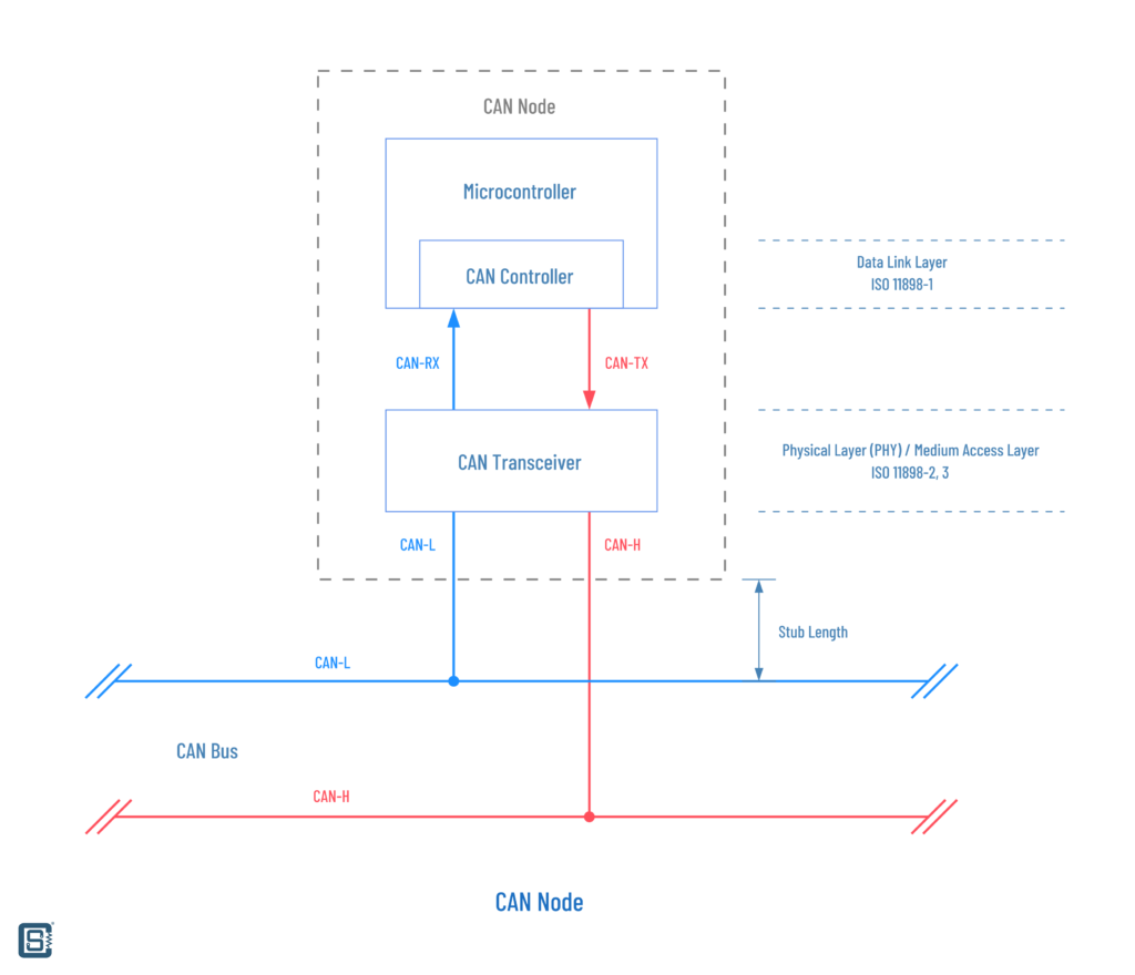
The CAN-H and CAN-L lines are not equivalent to CAN-RX or CAN-TX. A CAN Controller sends data to the CAN Transceiver through the CAN-TX pin, and receives data through the CAN-TX pin. The CAN Transceiver will also have RX and TX pins to connect to the CAN Controller pins. ESP32 has a single CAN Controller inside, that supports both standard and extended formats. But ESP32 doesn’t have an integrated CAN Transceiver. That means we need to add an external CAN Transceiver that supports 3.3V logic input for the RX and TX lines.
There are no specific limitations to how many CAN nodes can be connected to a single bus. The maximum number of CAN nodes depends on the bus design, speed, distance, etc. Every CAN node will add some capacitance to the line which will eventually limit the speed and the number of CAN nodes on a bus. Every CAN transceiver also has a limited drive strength that also limits the length of the bus. The length of wire that connects a CAN node to the bus is called Stub Length. It should be kept as short as possible.
Acceptance Filter
Since CAN is a shared bus and there is no concept of Central-Peripheral nodes, any node can initiate a data transfer (data broadcast) as soon as it wins the bus arbitration. Every other CAN node can receive and check the incoming data. But there can be a problem; if all nodes can receive the data from the bus, then each node will have to receive the data, save it to its buffer and check if the message is relevant to that node. It doesn’t make sense to spend time on doing that when none of those data is relevant to a node. For that reason, every CAN controller has an Acceptance Filter inside which a user can configure. The filter will automatically discard any messages that are not relevant to the user. We can program, for example, the specific ID or the range of IDs we want the data from. Once we have configured that, we only have to respond when relevant data comes in, which is usually done through some interrupts. This saves time for everyone.
Cabling
If you are designing a PCB with CAN bus lines, then the tracks must be regarded as a differential line with a characteristic impedance of 120 Ω. For cabling, typically a twisted pair is used for CAN-H and CAN-L signals. An extra wire or pair may be used for the GND connection. The cable can be shielded or unshielded. If it is shielded, only one end of the shield must be connected to the GND or Earth. For basic experimentation, you can use short wires such as jumper cables. A DE-9 or similar connector is used for CAN interconnections. Depending on the cable length and type, the maximum distance or speed may be limited as shown in the table below.
| Bus Speed | Bus Length | Cable Stub Length | Node Distance |
|---|---|---|---|
| 1 Mbps | 40 meters (131 feet) | 0.3 meters (1 foot) | 40 meters (131.2 feet) |
| 500 kbps | 100 meters (328 feet) | 0.3 meters (1 foot) | 100 meters (328 feet) |
| 100 kbps | 500 meters (1640 feet) | 0.3 meters (1 foot) | 500 meters (1640 feet) |
| 50 kbps | 1000 meters (3280 feet) | 0.3 meters (1 foot) | 1000 meters (3280 feet) |
CAN FD
So far we have been explaining the widely used CAN standards with two speeds – High-Speed and Low-Speed (FT). But one thing we can certainly expect with the evolution of communication interfaces is that they will get faster and smarter. That has also happened with CAN in the form of CAN-FD which stands for CAN Flexible Data. CAN-FD offers much higher speeds with the ability to adjust data rates dynamically. CAN-FD can push data up to 8 Mbps and the data payload size has been increased to 64 bytes from 8. That makes it obvious that CAN-FD is not compatible with older CAN standards. To use CAN-FD, you need supported CAN controllers and transceivers. CAN-FD has an improved frame format and sending them through a normal CAN bus will be perceived as an error. Most modern vehicle systems have moved from CAN to CAN-FD. Regardless of the changes, CAN-FD controllers and transceivers can function as normal CAN devices if configured so, and support both standard and extended IDs. We will cover CAN-FD in another post. For now, all CAN references mean normal CAN.
CAN Protocols
If you thought CAN and CAN-FD are the only things you “can” find out there, then you are innocent and wrong. There are so many different flavors of practical CAN implementations tailored for some specific application. And there are many protocols that run on top of different CAN versions and form high-level communication interface suites with special data formats, wiring and other rules. It is highly likely that you will encounter CAN as one of those high-level protocols instead of raw-CAN. A few of the popular protocols/standards are,
- SAE J1939 – An OBD (On-Board diagnostics) protocol suite built on top of CAN and is intended for heavy-duty vehicles such as trucks, buses, hydraulic systems, etc.
- OBD-II (OBD-2) – On-board diagnostics (OBD) is a standard used in mainly cars to broadcast diagnostic and running information of all electrical, electronic, and mechanical systems.
- ISO 11783 (ISO Bus) – An SAE J1939-based protocol suite intended for agricultural machines such as tractors.
- ISO 15765-2 (ISO-TP) – ISO-TP (Transport Layer) allows larger data to be shared as packets with network-based addressing. It implements the Network Layer and Transport Layers of the OSI model.
- CANopen – An open protocol used mainly in the embedded system domain (industrial, medical, robotics etc) and provides addressing and data transport features.
ESP32 CAN Controller
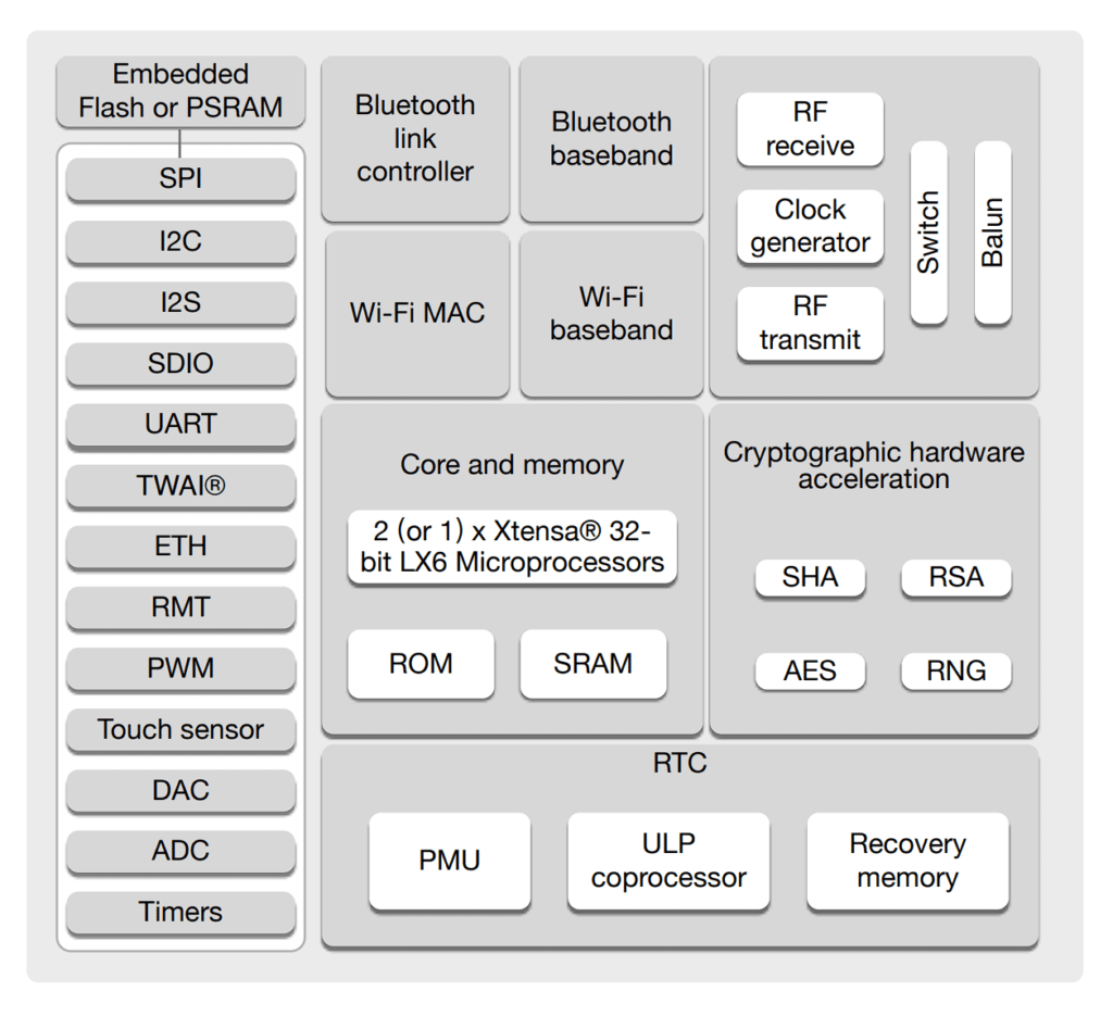
Espressif calls its CAN bus-compatible controller as TWAI (Two Wire Automotive Interface). The CAN controller is compatible with the standalone CAN controller SJA1000T from NXP. A standalone CAN controller is simply an external CAN controller that can be used to add CAN functionality to microcontrollers without integrated CAN. Espressif previously used to call TWAI as CAN and used the term for all its documentation and APIs. But some things changed after a while and all the latest docs and APIs refer CAN as TWAI. So when you see both TWAI and CAN relating to ESP32, understand that they both mean the same thing.
The best place to learn about TWAI of ESP32 is the ESP32 Technical Reference Manual which has a dedicated section for TWAI. The main features of the ESP32 CAN controller are,
- Compatible with ISO 11898-1 protocol (CAN Specification 2.0)
- Supports Standard Frame Format (11-bit ID) and Extended Frame Format (29-bit ID)
- Bit rates:
- from 25 Kbit/s to 1 Mbit/s in chip revision v0.0/v1.0/v1.1
- from 12.5 Kbit/s to 1 Mbit/s in chip revision v3.0/v3.1
- Multiple modes of operation
- Normal
- Listen Only (no influence on the bus)
- Self Test (transmissions do not require acknowledgment)
- 64-byte Receive FIFO
- Special transmissions
- Single-shot transmissions (does not automatically re-transmit upon error)
- Self-Reception (the TWAI controller transmits and receives messages simultaneously)
- Acceptance Filter (supports single and dual filter modes)
- Error detection and handling
- Error counters
- Configurable Error Warning Limit
- Error Code Capture
- Arbitration Lost Capture

As usual, we have a set of configuration registers, buffers, interrupts, and an acceptance filter among other things. There are four pins associated with the TWAI block.
- RX and TX – CAN Controller receive and transmit lines. They should be connected to the TX line and RX line of the CAN Transceiver respectively. Both signals interpret a dominant bit (
0) asLOW(0V) and a recessive bit (1) asHIGH(3.3V). - CLKOUT – The CLKOUT signal line is optional and outputs a prescaled version of the controller’s source clock.
- BUS-OFF – The BUS-OFF signal line is optional and is set to a
LOWlogic level (0V) whenever the TWAI controller reaches a bus-off state. The BUS-OFF signal line is set to aHIGHlogic level (3.3V) otherwise.
All four signals can be mapped to any compatible GPIO pin of the microcontroller which is a nice thing about ESP32. To use the CAN controller of the ESP32, we need a CAN transceiver. ESP32 does not have an integrated CAN transceiver and therefore we must use an external one. For this tutorial, we will use a CAN transceiver module based on the TJA1051 High-Speed CAN transceiver from NXP.
If you are new to ESP32, we have a getting started tutorial for complete beginners where we use the popular DOIT ESP32 DevKit V1 board for the demo.
Getting Started with Espressif ESP32 Wi-Fi & Bluetooth SoC using DOIT-ESP32-DevKit-V1 Development Board
TJA1051 High-Speed CAN Transceiver
TJA1051 is a High-Speed CAN transceiver from NXP. Available in different 8-pin SMD packages, it supports speeds up to 5 Mbps. Yes, it also supports CAN-FD. TJA1051 supports dual supply voltages, one for the transceiver section (VCC) and one for the logic section (VIO). VCC should be from 4.5-5.5V and VIO can be from 2.8-5.5V. We will use 5V as VCC and 3.3V as VIO.
Features
- Fully ISO 11898-2:2003 compliant
- Timing guaranteed for data rates up to 5 Mbit/s in the CAN FD fast phase
- Suitable for 12 V and 24 V systems
- Low Electro Magnetic Emission (EME) and high Electro Magnetic Immunity
- VIO input on TJA1051T/3 and TJA1051TK/3 allows for direct interfacing with 3 V to 5 V microcontrollers (available in SO8 and very small HVSON8 packages respectively)
- EN input on TJA1051T/E allows the microcontroller to switch the transceiver to a very low-current Off mode
- Available in SO8 package or leadless HVSON8 package (3.0 mm × 3.0 mm) with improved Automated Optical Inspection (AOI) capability
- Dark green product (halogen free and Restriction of Hazardous Substances (RoHS) compliant)
- AEC-Q100 qualified
- Functional behavior predictable under all supply conditions
- Transceiver disengages from the bus when not powered up (zero load)
- High Electro-Static Discharge (ESD) handling capability on the bus pins
- Bus pins protected against transients in automotive environments
- Transmit Data (TXD) dominant time-out function
- Undervoltage detection on pins VCC and VIO
- Thermally protected
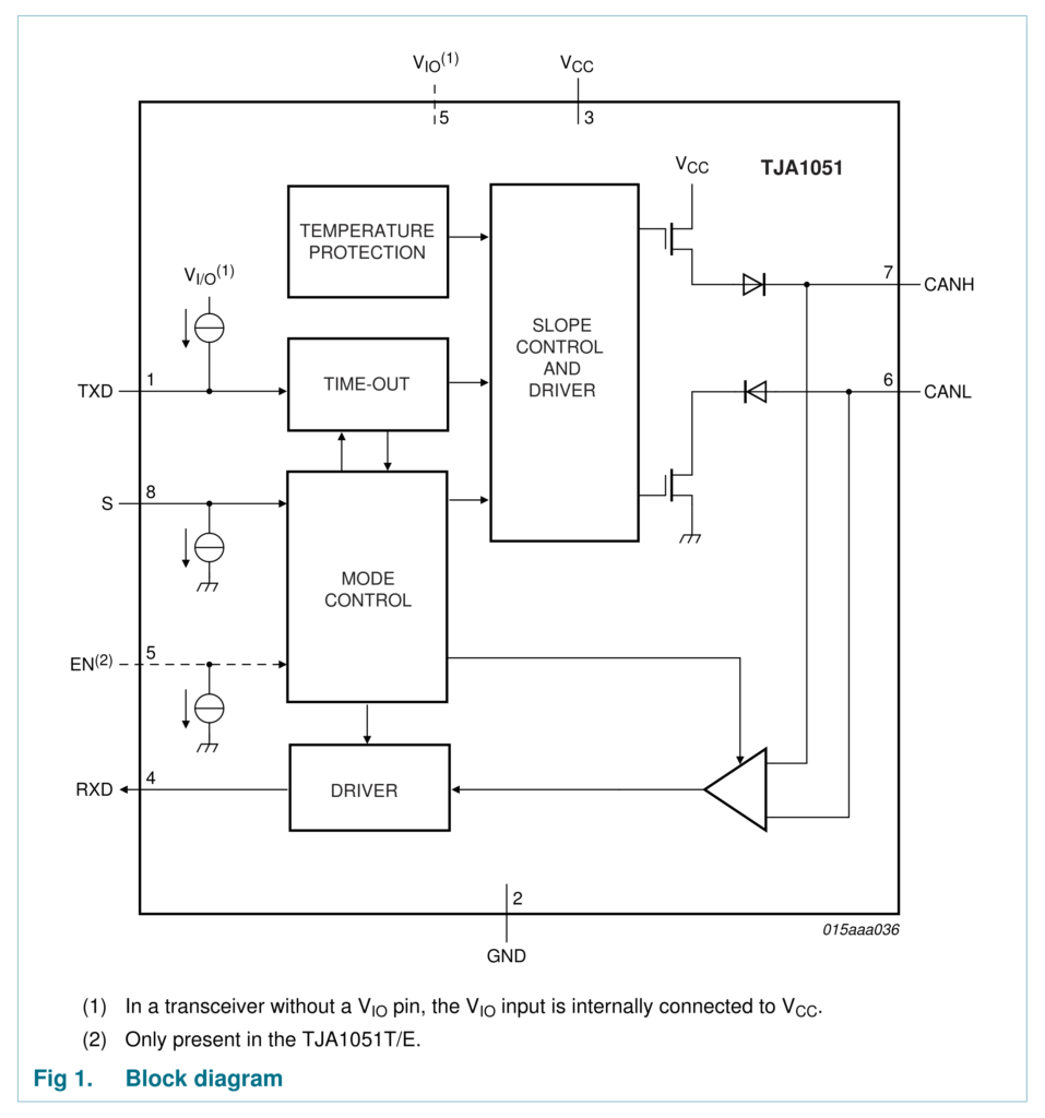
Block Diagram
Pinout
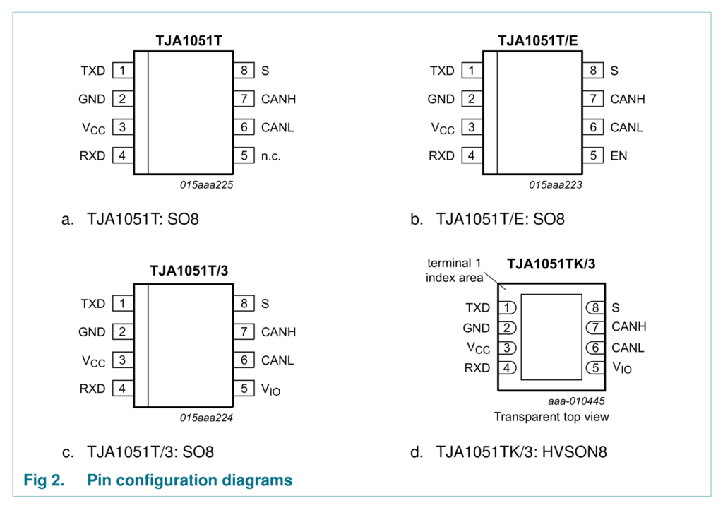
| Symbol | Pin | Description |
|---|---|---|
| TXD | 1 | Transmit data input |
| GND | 2 | Ground |
| Vcc | 3 | Supply voltage |
| RXD | 4 | Receive data output; reads out data from the bus lines |
| NC | 5 | Not connected in TJA1051T version |
| EN | 5 | Enable control input in TJA1051T/E only |
| VIO | 5 | Supply voltage for I/O level adapter. TJA1051T/3 and TJA1051TK/3 only |
| CANL | 6 | LOW-level CAN bus line |
| CANH | 7 | HIGH-level CAN bus line |
| S | 8 | Silent mode control input. HIGH = TRX off, LOW = TRX on |
CJMCU-1051

CJMCU-1051 is a TJA1051 breakout module from CJMCU, which is a brand that creates modules and breakout boards in purple colors. One module costs around INR 180 and we bought them from iFuture. But the IC used on the module only has “TJA1051” labeled on it. There are no T or T3 suffixes, without which we can’t know which variant of the chip it is. The board also has NC printed on the top for the 8th pin, but VIO on the other side. That made it more confusing. So I did some testing by hooking up the VCC to 5V, GND and NC to 3.3 and checked the idle voltages on the RX and TX lines. They both had 5V in the idle state which means, the chip variant is TJA1051T with no separate VIO supply. That’s kind of bad because we are going to use ESP32 which is a 3.3V MCU. So we must use a level shifter for the testing. You can also use simple voltage dividers. The idle voltages of the CANL and CANH lines will be 2.5V by the way. Following is the schematic of the CJMCU-1051 module. As you can see, the S control pin (pin 8) is connected to GND via a 10K resistor. This means, the CAN transceiver is always on by default.

Wiring
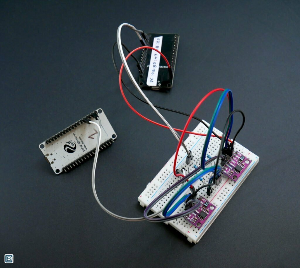
We need two ESP32 boards and two CAN transceivers for this experiment. Connect all the pins as shown below. Note that the CAN-RX and CAN-TX pins should be connected to CRX and CTX respectively. It is different from the convention used for UARTs. We are using 6.8K resistors in series with RX and TX lines to be safe with the different voltages. You can also use a dedicated four-channel level-shifter module. If you need a complete pinout reference for ESP32, we also have a dedicated page for that.

DOIT ESP32 DevKit V1 Wi-Fi Development Board – Pinout Diagram & Arduino Reference
Arduino Code
For the Arduino framework, we will use Sandeep Mistry‘s Arduino-CAN library that supports MCP2515 standalone controller from Microchip as well as the ESP32’s integrated CAN controller. You can install this library straight from the Arduino IDE by searching for “can”.
The library comes with many examples, and we have combined the Sender and Receiver sketches together in the code below. In the loop section, just need the functionality you need.
//==================================================================================//

#include <CAN.h>

#define TX_GPIO_NUM   21  // Connects to CTX
#define RX_GPIO_NUM   22  // Connects to CRX

//==================================================================================//

void setup() {
  Serial.begin (115200);
  while (!Serial);
  delay (1000);

  Serial.println ("CAN Receiver/Receiver");

  // Set the pins
  CAN.setPins (RX_GPIO_NUM, TX_GPIO_NUM);

  // start the CAN bus at 500 kbps
  if (!CAN.begin (500E3)) {
    Serial.println ("Starting CAN failed!");
    while (1);
  }
  else {
    Serial.println ("CAN Initialized");
  }
}

//==================================================================================//

void loop() {
  // canSender();
  canReceiver();
}

//==================================================================================//

void canSender() {
  // send packet: id is 11 bits, packet can contain up to 8 bytes of data
  Serial.print ("Sending packet ... ");

  CAN.beginPacket (0x12);  //sets the ID and clears the transmit buffer
  // CAN.beginExtendedPacket(0xabcdef);
  CAN.write ('1'); //write data to buffer. data is not sent until endPacket() is called.
  CAN.write ('2');
  CAN.write ('3');
  CAN.write ('4');
  CAN.write ('5');
  CAN.write ('6');
  CAN.write ('7');
  CAN.write ('8');
  CAN.endPacket();

  //RTR packet with a requested data length
  CAN.beginPacket (0x12, 3, true);
  CAN.endPacket();

  Serial.println ("done");

  delay (1000);
}

//==================================================================================//

void canReceiver() {
  // try to parse packet
  int packetSize = CAN.parsePacket();

  if (packetSize) {
    // received a packet
    Serial.print ("Received ");

    if (CAN.packetExtended()) {
      Serial.print ("extended ");
    }

    if (CAN.packetRtr()) {
      // Remote transmission request, packet contains no data
      Serial.print ("RTR ");
    }

    Serial.print ("packet with id 0x");
    Serial.print (CAN.packetId(), HEX);

    if (CAN.packetRtr()) {
      Serial.print (" and requested length ");
      Serial.println (CAN.packetDlc());
    } else {
      Serial.print (" and length ");
      Serial.println (packetSize);

      // only print packet data for non-RTR packets
      while (CAN.available()) {
        Serial.print ((char) CAN.read());
      }
      Serial.println();
    }

    Serial.println();
  }
}

//==================================================================================//
We are using GPIO21 as TX pin and GPIO22 as RX pin for this example. But you can change it to any GPIO pins. To set a custom pin for the CAN controller, we can use the API function setPins(). After that, we can initialize the CAN controller with begin() function by also passing the nominal bit rate. We are using 500E3 here which is 500 kbps.
In the canSender() function, we will send two types of CAN messages. The first one is a standard message with 8 bytes of data payload and a standard ID (11-bit) of 0x12. We can use beingPacket() to start a new message by passing the ID and then use write() function to write any messages. Make sure to limit the data to 8 bytes. The data length (DLC) will be automatically calculated from the data you are sending. Finally use endPacket() to send the message. Just after sending a normal data frame, we will send an RTR packet requesting for 3 bytes of data. beginPacket() function has a few overloads and we can send additional parameters as we need. For an RTR message, the third parameter should be true.
In the canReceiver() function, we will continuously check for new incoming CAN messages. If we receive a message, the packetSize will return a non-zero value. We will then check the packet type and use the read() function to read the CAN message data.
Sandeep has created an intuitive set of APIs for all the basic CAN functions. You can check out the complete API set here. Since we have already explained most of the things you need to know about CAN, you will not find it difficult to understand what each function or parameter does. If you run into any issues, please let us know about them in the comments.

CAN Debugging
Just like any other digital interface, we can use a Logic Analyzer to see the data flowing through a CAN bus in real-time. A cheap 24MHz logic analyzer can also do the job. Some DSOs (Digital Storage Oscilloscope) also have logic analyzers or decode functions. There are also specialized CAN adapters. The difference between a CAN Adapter and a typical logical analyzer is that a logic analyzer needs to be connected to the CAN-RX and CAN-TX lines in order to capture the data, because a logic analyzer can’t read differential signals. But a CAN adapter can convert the differential signals to digital data and can be used to extract data from a CAN bus directly.
Below is a screenshot of CAN data captured from CAN-TX and CAN-RX lines using a 24MHz 8-Channel logic analyzer we bought for INR 500. We used the Saleae Logic 2 software for capturing and decoding the data. You can see the entire CAN message with standard ID 0x12 followed by an RTR message.

Additionally, you can use the official ESP-Prog to debug your ESP32 CAN projects and fix the issues in your code. Check out our following tutorial for that.
Debugging ESP32 Arduino & ESP-IDF Projects using ESP-Prog and PlatformIO
Troubleshooting
You may run into many issues while trying to get the CAN communication working. We receive emails asking for help with troubleshooting. Below are a few of the known or expected issues and their solutions or troubleshooting tips.
That’s all for this tutorial. We hope we have been able to give you a good overview of the CAN interface. There are still more things to learn about CAN and you can check out the reference links we have added for more information. If you have any suggestions to improve this post or found any errors, please let us know in the comments.
Links
- CAN Bus – Wikipedia
- ESP32 Technical Reference Manual – TWAI [PDF]
- Two Wire Automotive Interface (TWAI) – ESP32
- CAN Errors – CSS Electronics
- Arduino-CAN – Sandeep Mistry
- CAN Bus 2.0 Specifications – Bosch [PDF]
- SJA100T – Standalone CAN Controller
- TJA1051 High-Speed CAN Transceiver
- CJMCU-1051 TJA1051 CAN Transceiver Module – Buy
- 24 MHz 8-Channel USB Logic Analyzer – Buy
Short Link
- Short URL to this page – https://circuitstate.com/esp32can


I have a weird thing about the SN65HVD230 in combination with the ESP32. When I send an 29-bit message, the prio bit is missing on the receiving side.
Message example for sending:
twai_message_t message;message.identifier = 0xE0FFFF20;
message.extd = 1;
message.data_length_code = 8;
message.data[0] = 0x01;
message.data[1] = 0xFF;
message.data[2] = 0x00;
message.data[3] = 0x00;
message.data[4] = 0x00;
message.data[5] = 0x00;
message.data[6] = 0xFF;
message.data[7] = 0xFF;
On the receive side the
message.identifieris0xFFFF20so theE0is missing.Does anyone have an idea what this is about?
Or is the prio bit automatically removed by the canbus receiver?
ESP32SJA1000.cpp was not completely correctly pasted so here it is:// Copyright (c) Sandeep Mistry. All rights reserved.
// Licensed under the MIT license. See LICENSE file in the project root for full license information.
#ifdef ARDUINO_ARCH_ESP32//#include "esp_intr.h"
#include "soc/dport_reg.h"
#include
#include
#include
#include "driver/gpio.h"
#include "esp_intr_alloc.h"
#include "ESP32SJA1000.h"
...
Thanks for posting your question. We have truncated the long code you posted to the keep the thread small. Could you please post the code in GitHub Gist and post a link here?
I am trying to use TJA1050 to communicate between two esp wroom 32. i had this error message:Arduino: 1.8.19 (Windows 10), Board: “ESP32 Wrover Module, Default 4MB with spiffs (1.2MB APP/1.5MB SPIFFS), QIO, 80MHz, 921600, None, Disabled”
D:\Program Files (x86)\Arduino\arduino-builder -dump-prefs -logger=machine -hardware D:\Program Files (x86)\Arduino\hardware -hardware C:\Users\tabre\AppData\Local\Arduino15\packages -tools D:\Program Files (x86)\Arduino\tools-builder -tools D:\Program Files (x86)\Arduino\hardware\tools\avr -tools C:\Users\tabre\AppData\Local\Arduino15\packages -built-in-libraries D:\Program Files (x86)\Arduino\libraries -libraries C:\Users\tabre\Documents\Arduino\libraries...Please can you help me solve this issue? Thanks
Hi! I’m trying to use the example code, but the
CAN.endPacketfunction does not work. It runs through the whole code, but can’t execute the line “return 1“. I have seen that it is incapable of returning a true/HIGH/1, but it can return a false/LOW/0. Do you know what causes this, and can I fix it? This means the code is stuck, and never moves past theCAN.endPacketfunction.I’m using an ESP-WROOM-32 Devkit V1. I have the MCP2561 CAN tranciever, so different from you, but I believe the problem currently lies with the code.
Hi Erlend. The
endPacket()function waits for all of the previously sent packets to be transmitted completely. If the transmission is not successful, it can create a dead loop. Make sure you have a second active CAN node connected to your device. If there are no other CAN nodes to receive the data you are sending, or if the wiring is not proper, the sketch will be stuck at “Sending packet …” message state. Hope that helps.Hi again! Unfortunately it still does not work. I have made sure to upload receiver code to one ESP, and transmitting code to the other, and power both when I’m trying to send a packet. I have also double and triple checked wiring, and my fellow students have checked as well. I’m looking at the circuit with an oscilloscope, and the TX pin (D21) does not output a varying signal, only a constant HIGH signal. I tried to create a varying signal with that pin, using digitalWrite() function, and this works, so the ESP and D21 pin seems to be working. Do you have any idea what the problem may be?
Without actually seeing your setup we can not assess what is wrong. Please check out the Troubleshooting section for possible issues and workarounds. Make sure you are using the right library first. There should not be any pin assignment conflicts when using the GPIO pins for CAN. Then check the wires, if you have them, by doing continuity tests. Some jumper cables come bad. Then upload the CAN_Sender code to one of the boards and see if any data is coming out. We do not know which ESP32 boards you are using. But if the ESP32 chip is faulty, CAN won’t work even if other functions do. Try a different board if nothing works.
Thanks for this elaborate and well explained tutorial. I am using a Lilygo SIM800L and CJMCU-1051 as it is in this tutorial, connected to GPIO PIN 21 to CRX and 22 to CTX without any resistors. The issue I am facing is when I compile the library arduino-can. It throws error –
fatal error: esp_intr.h: No such file or directory.Upon reading other posts this header file has been depreciated and replaced withesp_intr_alloc.hwhich throws several other errors such as – In member function'virtual int ESP32SJA1000Class::begin(long int)':. I have no idea where to go from here. Any help will be much appreciated.Regards,
AJ
Hi Ajay. Thanks for your feedback. Compatiblity issues can be very difficult to manage if the open-source softwares are not maintained actively. We will look into the issue and see if we can find a workaround. One thing you can do is to downgrade your SDKs or frameworks to older versions and check if it is working for you.
We were able to compile the CAN-Sender-Receiver sample code for the FireBeetle-ESP32-E board using the following versions of the dependencies.
framework-arduinoespressif32 @ 3.20014.231204 (2.0.14)tool-esptoolpy @ 1.40501.0 (4.5.1)
toolchain-xtensa-esp32 @ 8.4.0+2021r2-patch5
CAN @ 0.3.1+sha.a1cd301
We used PlatformIO for this. The build was successful. Please check if your target configuration are correct.
Thanks for your reply. I have updated Arduino IDE and it is picking up the libraries now.
Just for an update, I am not getting any reading in serial monitor as of now. However, I can read data on PCAN. I am still troubleshooting I will keep you updated.
I tried to reply immediately but the site wasn’t letting me then, hopefully it will work this time.
Here is an update. I have tried the following;
Arduino IDE 1.8.19 (Windows Store 1.8.57.0) – Compiles/Uploads – Serial.println(ESP_OK) returns 0.
Arduino IDE 2.3.2 – Compiles/Uploads – Serial.println(ESP_OK) returns 0.
Changed board and verified the boards by flashing internal LED (GPIO2) on both boards.
AZ-Delivery ESP32-Wroom-32 module – IDE Board “ESP32 Dev Module” – Same result
ESP32-Wroom-32 module Devkit V1 – IDE Board “ESP32 Wrover Module -Same result
Used libraries individually on both boards and IDEs mentioned above.
1) #include “driver/twai.h”
2) #include
3) #include
4) #include looks more promising (see below)
When I monitor the oscilloscope I get voltage high, no data being transmitted.
I can read 3.3V on both WCMCU-230 and CJMCU1051 CAN modules.
#include although I dont read anything on PCAN or Arduino Serial monitor, I dont get any errors. I have modified baud rate, tried 250kbits/s (where I cant see CANOpen device’s heartbeat for reference – I do not see messages from CAN transceiver).
If this is not a library issue I don’t know what is. I will keep on troubleshooting and keep you updated (its a shame I can’t share images here)
Regards
Censored libraries – Didn’t realise angle brackets arent allowed
Used libraries individually on both boards and IDEs mentioned above.
1) #include “driver/twai.h”
2) #include “CAN.h”
3) #include “ESP32CAN.h”
4) #include “ESP32-TWAI-CAN.hpp” looks more promising (see below)
#include “ESP32-TWAI-CAN.hpp” although I dont read anything on PCAN or Arduino Serial monitor, I dont get any errors. I have modified baud rate, tried 250kbits/s (where I cant see CANOpen device’s heartbeat for reference – I do not see messages from CAN transceiver).
Regards
The first thing you can do is to make sure your hardware setup works correctly. This can be verified by having two similar CAN nodes (for example, a combination of the ESP32 board and a CAN transceiver) and connecting them together and run the CAN-Sender and CAN-Receiver code. Have you done such a test?
Though I just found this page I must say it is the most comprehensive and well explained articles on CANBUS I have found yet to date. Really good work Sir, this information is proving quite helpful.
Thank you.
Thank you.
How many CAN ids can esp32 read in a single shot?
Not sure what you meant by “single shot”, but the ESP32 CAN controller can read any messages being transmitted through the CAN bus it is connected to. Every nodes on a CAN bus can see others’ transmissions as well as their own. So there is not limit to how many IDs you can read at a given time frame. It depends on how fast you are going to process and return the response. This is in addition to the arbitration, error-correction etc processes.
Hey, thanks for providing those nice overviews for different topics :).
I’m currently working on a smaller project where i try to log two different CANs. As i have noticed from the comment section, it would be easily possible to just duplicate the instantiation of either ESP32SJA1000Class or MCP2515Class when using the CAN library. But i’m currently struggling with setting up the whole hardware. As of now i bought an ESP32 AZdelivery DevKit C V4 (https://www.amazon.de/dp/B08BZGC22Q) as well as two of the CAN Transceivers SN65HVD230 (https://www.amazon.de/dp/B0B5DTN62K). Now I understood there is no possibility to use both CAN tranceivers on one ESP32 board since there is only 1 CAN Controller, right?
Which CAN boards would you recommend, so that im not forced to use two ESP boards.
Thanks in advance, and keep up the good documentation 🙂
Thank you. If you want to enable a single ESP32 with two separate CAN buses, then you can include an extra standalone CAN controller, for example MCP2515, interfaced through SPI. Then you will have one internal CAN controller and one external. Even if you need more CAN controllers, you can add them to the same SPI interface but with different CS pins for each. Check out this tutorial – https://copperhilltech.com/blog/esp32-triple-can-bus-application-through-adding-two-mcp2515-ports/
Well thanks for this article very detailed. İ want to learn a point esp32 s3 documants says “The TWAI controller is not compatible with ISO11898-1 FD Format frames, and will interpret such frames as errors”
What you think about this docs note. Well if esp32 not supprt FD , and new cars working with FD.
You are right. Current generation of ESP32 SoCs do not support CAN-FD and can not generate or receive CAN-FD packets. You will need an external CAN-FD controller for this. Fortunately, many manufactures have standalone CAN-FD controllers, for example TCAN4550 from TI, that you can interface with ESP32 via SPI or some other interface. If you want ton use CAN-FD with ESP32, that is the only option.
Hi i have a Audi 2016 for repear , ABS ESP AIRBAG and two other from propulsion bus lights on display , i want to simulate for take of the screen …..please tell if you have some tools for do that , regards
I don’t think I understand what you are trying to describe. Try explaining it in more detail.
Hello,
Without doubt, the best and most comprehensive documentation on CANbus.
What I’d like to know is whether there’s any disadvantage to replacing TJA1051 with SN65HVD230 (advantage/disadvantage?).
Many thanks
Thank you, Claude.
Which CAN bus transceiver to use depends on the application requirements. Since TJA1051 and SN65HVD230 are products from different manufacturers, we can not also have a one-to-one comparison of all the features. But the obvious difference between them is the speed; SN65HVD230 supports data rates up to 1 Mbps and the TJA1051 can go up to 5 Mbps. The supply voltage range of TJA1051 is also larger.
Hello I am testing your code but when I send the message I don’t get a print saying “done”, I get the feeling that trying to send the characters but the
can.endPacket()doesn’t work, can you help me?Thanks a lot.
Regards
Are you able to send any messages to the other end? If you have a logic analyzer, you can hook it to the CAN RX pin and see if any data being captured. Also check the new troubleshooting section added to our tutorial.
Also,
CAN.setPins();is giving me trouble. Seems that the CAN object was not created or something. Should this beCAN_device_tCAN;?If you are using Sandeep Mistry‘s Arduino-CAN library, then a
CANobject (of typeESP32SJA1000Class) will be already created when you include theCAN.hfile in your code. You can create additional CAN objects using theESP32SJA1000Classtype.Hello,
Thank you for the post it has been extremely helpful, but I have a few questions. If I am using CAN and I2C on the same board will there be any interferance? Currently, I have opened two i2c buses on pins 15, 23 and 18, 19. For some reason if I try to use CAN on pins 4, 5 I get a corrupted can message. If I use the single default i2c port, pins 21 and 22, then pins 4 and 5 for CAN I dont have any trouble. Any insight as to why this might be happening? Also I am using adafruit libraries for communication with sensors.
Thanks!
Brandon
I2C and CAN (TWAI) are separate communication interfaces/peripherals and have dedicated resources. So using I2C and CAN at the same with ESP32 should not cause any issues. The problem is likely related to pin assignments. The peripheral functions can be mapped to any GPIO pins in ESP32. The Arduino ESP32 core has default pin assignments. The libraries you are using might also come with default pin assignments. So if a single pin is assigned with multiple functions, the error may not be apparent during compilation and the code can still compile. But during the execution, there will be communication errors. You can do the following to narrow down the issue.
1. Make sure the functions mapped to the GPIO pins are exclusive.
2. Check if any libraries are mapping pins with other functions than intended.
3. Assign all pin functions explicitly (using
setPins()function or some constructor) before initializing any interfaces or library objects.4. Some libraries will warn about pin assignment conflicts during compilation. Check the compilation log to find any such warnings and locate the errors.
The SanseepMistry library does not work with later ESP32 boards, like the Devkit V4. There is not data sent to the GPIO pins no matter which ones you choose in the code. Any idea how to resolve this?
Do you have a link to the product page of the exact Devkit V4 board you are using?
Thank you for the post.
Does the built-in CAN Controller use the SPI ?
The internal CAN Controller of the ESP32 does not use SPI. CAN Controller and SPI are different communication interfaces/peripherals inside the chip and work entirely differently. The main signals coming in/out of the CAN Controller are CAN_RX and CAN_TX which you can wire to an external CAN Transceiver chip, just like what we have shown. Hope that clears the confusion.