What is RS-485 & How to Use MAX485 with Arduino for Reliable Long-Distance Serial Communication
Learn about the industry-favorite RS-485 (EIA-485) wired communication interface standard and learn how to interface the MAX485 module with Arduino.

If you have used any microcontrollers before, you should be familiar with the UART interface. The Universal Asynchronous Receiver Transmitter (UART) is a serial communication interface found inside most modern microcontrollers. It sends any data in the form of a sequence of digital 1s and 0s, just like Morse Code. Similarly, there are other serial interfaces like SPI (Serial Peripheral Interface), I2C (Inter-Integrated Circuit), and CAN (Controller Area Network). Even the USB we use every day is also a serial interface expanded as Universal Serial Bus. We can use these serial interfaces for interfacing sensors, RF transceivers, displays, etc. Everything will be fine when all of the things you want to interface with are in close proximity, within a meter or so. If you have ever tried to extend the UART or SPI signal wires, you must have noticed that they were not working as expected. There will be data loss, data corruption or even the interface can stop working.
The issues arise because the reliability of electrical signaling of digital data over any communication link depends on many [so-far-ignored] factors such as wire length, impedance, frequency, noise, interference, etc. None of these things mattered much when we were using UART or SPI when the devices were close together. To communicate over long distances reliably, we need better interfaces and communication links. RS-485 is just that type of interface that helps us deal with all of the issues stated earlier, and allows us to communicate over long cables and with devices situated many hundreds of meters away. In this tutorial, we will learn what an RS-485 interface is, how it works, its advantages, and its limitations. At the end of the tutorial, we will also learn how you can use the RS-485 with your Arduino and Arduino-compatible boards.
Need RS-485 or Modbus for your project?
CIRCUITSTATE can design and develop complete electronic products incorporating communication interfaces and protocols like RS-485, RS-232, 4-20mA, HART, Ethernet, MODBUS, etc. on all hardware platforms and frameworks, with robust performance. Contact us today to share your requirements.

Things Required
You will need the following things to follow the examples shown in this tutorial.
- 2 × RS485-to-TTL Module (with MAX485 and CD4069)
- 2 × Any Arduino-compatible microcontroller board.
- 1 × Twisted-pair cable.
- Header pins
- Jumper cables
- 2-pin screw-terminals
What is RS-485?
RS-485 is an asynchronous serial communication bus standardized as TIA-485(-A) or EIA-485. The RS stands for “Recommended Standard” which is a set of communication interface standards maintained by the Electronic Industries Alliance. RS-485 uses a two-wire balanced cabling such as twisted pair. The cable can extend up to 1200 meters and a maximum of 32 devices (at Unit Load) can connect to the same bus. Data is sent serially over the cable and the transmitted electrical signal will be differential in nature. Unlike single-ended signals such as UART, differential signaling allows RS-485 to reject common mode (CM) noise. Combined with the possibility of long-distance communication, RS-485 is extensively used as a robust communication link for industrial applications where the operating environment can be extremely noisy.
Topology
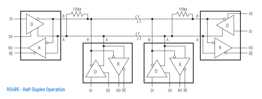
RS-485 employs a bus topology as its network structure. Following is an example of a typical half-duplex RS-485 bus with 4 devices. The devices/nodes are connected in a daisy-chain manner. Even though other topologies are possible, this configuration yields the best performance. The line length to a node (called stub length) must be short as possible.
Signaling
There are two signal lines in an RS-485 bus; signals A and B. A and B form a single differential line required for the RS-485 interface. The electrical properties of this line are specified by the EIA-485 standard and every manufacturer has to conform to the standard. During active communication, the voltages on lines A and B will be opposite in polarity (with respect to a reference level). For example, if A is at a positive level, then line B will be at a relatively negative level, and vice versa. Both A and B lines can not be in the same state during active communication, because that defeats the purpose of using differential signaling.

In the above illustration, signal A is shown in red and B in blue. REF is the reference voltage which can be what is set by the user. REF doesn’t necessarily have to be 0V. IDLE+ and IDLE- are idle voltage levels when A and B will be at when the bus is not actively driven. When A is at V+, then B is at V-. When the polarity changes, A will be V- and B will be V+. For such a differential line, we always measure the difference in the voltages on the lines. The Bus Logic graph shows the actual data we are sending.
Let’s assume V+ is +5V and V- is 0V and REF is 2.5V. Then the differences between A and B are,
If A = 5V and B = 0V, then A - B = +5V (A > B)
If A = 0V and B = 5V, then A - B = -5V (A < B)
The state when A becomes less than B (A < B) is called a Mark or OFF or Logic 1 and the state when A becomes greater than B (A > B) is called a Space or ON or Logic 0. Sounds confusing? Let’s summarize that in a table.
| Relative Voltage | Example Voltage Levels | Difference Level | Logic State |
|---|---|---|---|
| A < B | A = 0V, B = 5V | -5V (Negative) | Mark/OFF/1 |
| A > B | A = 5V, B = 0V | +5V (Positive) | Space/ON/0 |
So essentially, both lines carry the same information but in opposite polarities. You can also think of A as a non-inverting input and B as inverting input of a differential amplifier. Because this is how manufacturers used to label differential amplifier pins. The EIA-485 document uses A, B, and C sequences for the labeling line interfaces. Some manufacturers also label A as + and B as –. Yet some others label A as A+ and B as B+. You can even find D+ (A) and D- (B). All you need to do is to make sure that all devices connected to an RS-485 line agree on the same convention. This is because if you swap A and B lines, all data on your line will also be reversed; all 0s become 1 and all 1s become 0. You can read more about the polarity conventions of differential signals here.
But why is the Negative level interpreted as logic 1 and the positive level as logic 0? That is another confusing aspect. The answer is convention. Interpreting negative voltage as logic 1 has been the convention and everybody continues to use it. So you also have to stick to that.
If it is a difference in voltages that only matters, then what is the allowed voltage on the lines? Because 5V – 0V and 5000V – 4995V produce the same difference of +5V, for example. The EIA-485 specifies that there should be a minimum difference of ±0.2V (±200 mV) between the lines for detecting the logic levels. In other words, a minimum difference of +200 mV can be considered as a Space/ON/0 and -200 mV can be considered as a Mark/OFF/1. For sending, the voltage difference should be at least ±1.5V. EIA-485 also specifies that the common-mode voltage (the voltage on each line with respect to a reference voltage known to all nodes) on the lines should be within -7 and +12V. This puts a maximum limit on the typically used voltage levels of +5V and 0V. This limit on the common mode voltage can be enforced with an optional line called SC (Signal Common) or GND or Reference (REF). This common line does not have to be the actual circuit GND of a device. It can be a separate common-mode reference point different from GND, as we will see later. Also, there are transceivers with higher common-mode voltage ranges for better robustness.

But why do we have to use differential signaling in the first place? That too in a varying range of signaling voltages? Will devices operating with different signal voltages connected to the same bus cause any problems? Let’s find the answers for them.
Every electrical cable or wire has some finite resistance, capacitance, and inductance to it. The cable is also physically routed through some other medium. When an electrical signal is traveling through a cable, the properties of the cable and the medium can influence the signal and cause it to lose its quality, which is called signal degradation. The resistance of a cable can, for instance, be characterized by the resistivity of a wire. That means, that at every unit length, the resistance of the wire to an electric current will increase. This increase in resistance can limit the maximum current we can supply and therefore a transmitted signal will lose its strength when traveling over a long cable. So when we try to increase the length of a cable for long-distance communication, our signals get weaker and the communication becomes unreliable.
Another issue is that when we increase the length of the cable, it becomes more susceptible to all types of electrical noises and interferences. If we are using a single-ended signal, the noise will induce spurious signals and that will corrupt the data traveling through the cable.
RS-485 solves these issues by using a differential communication line that can operate at a wide range of voltage and a small differential voltage for reading the signals. The -7 to +12V range corresponds to a voltage gap of 19V. A larger voltage allows for a longer cable length before the signals can degrade significantly. Even if the signals get weaker, we only need a differential voltage of just ±200 mV to reliably read the data from the bus. This is the reason why the RS-485 bus can be up to 1200 m in length. But there is another trade-off with long cables. The communication speed will decrease with an increase in cable length due to reactive effects. For example, a fast RS-485 transceiver can transmit at a rate of up to 35 Mbps over a 12 m cable. But this rate will drop to around 100 Kbps at a length of 1200 m. This limitation is due to some other characteristics of a transmission line.
The wide voltage range also means that all RS-485 transceivers conforming to the EIA-485 standard will have no trouble using or accepting different voltage levels on the same bus, as long as there is a minimum of ±200 mV differential voltage and the maximum voltages are within the specified limits.
Differential signaling helps the bus to reject common mode noise very efficiently. This is because when a noise signal gets induced on the cable, it affects both signal wires (A and B) equally if the lines are balanced (the reason why we need to use proper termination resistors). We already have seen that we only read the difference in voltages of the signal lines. This also helps us to basically subtract the equally induced signals as well. The EIA-485 standard does not specify the type of cable to use but a shielded or unshielded twisted pair is used widely. The standard also does not specify any specific connectors or pinouts to be used with RS-485. Industries, therefore, use the popular DB-9/DE-9 connector in most cases.

Transceiver Design
Every device connected to an RS-485 bus can act either as a Driver (transmitter) or Receiver. The circuit that drives or reads the line is actually an op-amp differential amplifier. That is why the drivers are represented by a triangle with two inputs and one output. The driver is a device that is currently using the bus for transmitting data. Even though there can be 32 drivers on a line, only one driver can be active at a time. This means, that only one device can transmit through a pair of RS-485 lines. Every other device on the network will act as a receiver at this time and can read all the data going through the bus. This type of communication line is called a multi-drop line. RS-485 can also be considered a multi-point line since any device can also act as a driver/transmitter by changing its role dynamically.

In the illustration, D stands for Driver and R stands for Receiver. You can also see the small circles at the end of some signals. It simply means any signal passing through that circle gets inverted. So a HIGH becomes LOW and a LOW becomes HIGH. In other words, circles represent inverting inputs/outputs, and no circle indicates non-inverting inputs/outputs. In addition to the A and B lines, there are four other signals coming out of a typical half-duplex RS-485 transceiver (the Driver and Receiver can be together called a transceiver). They are DI, DE, RO, and RE. Let’s see what each means.
| Signal Name | Description |
|---|---|
| A | Non-inverting Signal |
| B | Inverting Signal |
| DI | Driver Input |
| RO | Receiver Output |
| DE | Driver Enable |
| RE | Receiver Enable (Active LOW) |
To make your half-duplex RS-485 device a transmitter (driver) you need to pull both DI and RE pins to HIGH. Since RE is an active-low input, the driver mode gets selected. At this time, if you apply a positive voltage (single-ended) to the DI input, lines A will become LOW and B become HIGH. This is how you send binary data through an RS-485 bus. Any other device connected to the bus acting as a receiver can read the data you are sending. So at the other end, a receiver has to keep the DI and RE pins at LOW and read the output from the RO pin. The output from RO pin will be a single-ended signal. RS-485 drivers also use three-state logic where the outputs can be HIGH, LOW, and High-Z (High Impedance).

But when does a device determine it can use the bus for transmitting data? What happens when multiple devices decide to transmit at the same time? In such an event a data collision would occur leading to data corruption and loss. For this reason, the devices connected to an RS-485 have to mutually agree on when they can use the bus to transmit data. This can be achieved with a Server-Client scheme. There will be one device acting as a Server that tells all other devices when to transmit. The server can send a Request message on the bus along with a unique address that identifies another device on the bus. Since all Client devices can listen to this Request, the device with the requested ID can decide to respond to the Server’s request. This way the bus can be shared without any collisions. Data protocols such as Modbus use a similar Server-Client topology and a messaging system for reliable communication. If you want to learn more about the Modbus protocol and how to implement Modbus using RS-485 and Arduino, check out our following tutorial.
What is Modbus Communication Protocol & How to Implement Modbus RTU with Arduino
One thing should be obvious now; signals A and B can only be used to either transmit or receive at a time. This is referred to as half-duplex communication. RS-485 can be made into a full-duplex (transmit and receive at the same time) communication interface by employing two separate differential lines. Then one line can be used for transmitting and the other can be used for receiving. When you have two differential lines, each signal is labeled as A, B, Y, and Z.
| Signal Name | Description | Connects To |
|---|---|---|
| A | Non-inverting Receiver Input | Y |
| B | Inverting Receiver Input | Z |
| Y | Non-inverting Driver Output | A |
| Z | Inverting Driver Output | B |
EIA-485 also specifies adding termination resistors at the two farthest ends of the bus to prevent signal reflections and to balance the lines. The value of this resistor is 120 Ohms typically for cables with the same impedance. Other devices (drop points) do not require termination resistors.

Data Transmission
Finally, how do you use RS-485, say with a microcontroller? RS-485 interface can be added to your application circuit by using any RS-485 transceiver ICs. There are half-duplex (only one differential line) and full-duplex (two differential lines) configurations. Most applications only require half-duplex communication, including industrial applications. When interfaced with a microcontroller, you can use any GPIO pins to drive the DI, DE, RO, and RE signals of the RS-485 transceiver. You just have to make sure the IO voltage of the transceiver IC is compatible with the IO voltage of your microcontroller. Since we are dealing with serial communication, the easiest way to drive an RS-485 line is with the help of UART pins. The TXD pin of the UART will drive DI and the RXD pin read data from the RO pin. Even though a 2-line UART can operate in full-duplex mode, it can only work in half-duplex mode when used with a half-duplex RS-485 transceiver. The speed at which you can communicate through an RS-485 bus will depend on your UART speed (baudrate).
RS-485 transceivers are available at different speeds, packages, and working voltages. We will learn about a very popular MAX485 half-duplex transceiver IC from Maxim Integrated in the next section.
SC & Ground Connection
Even though RS-485 is a differential line and you might think only “two-wires” are required for creating a bus, it is not actually true in the practical sense. For short-distance communication, you will get away without using the Signal Common (SC) line. But for all practical applications that focus on reliability and safety, a common line is used to establish a common-mode reference to all connected nodes. Why this is important because the RS-485 bus can be hundreds of meters long and the devices can have different types of power sources and other characteristics. This can lead to large differences in common voltages at each node, and if the voltages are outside the limits, it can affect the functionality of the devices, in the worst case damage them. So there are practical aspects to be considered when wiring RS-485 lines. EIA-485 standard specifies a few ways of connecting the ground.
- Method 1 – In the first method, you can connect the SC of each node to the GND supply (Negative) of the local power supply. This assumes that the power supplies or the transceivers are not isolated ones. This method allows low Ground Potential Difference (GPD) to develop but may induce large Ground Current Loops (GCL). This method is suitable if the cable length is short and you are sure GPD will be small.
- Method 2 – The second method is to use a fuse and 100 Ohms 0.5W resistor in series between the GND and SC lines of each node. The resistor will limit the current and the fuse will protect against overcurrents. This method can lead to large GPD but loop currents will be small.
- Method 3 – The third method is to use Earth as the signal common. In this method, the SC pins of the nodes do not need to be connected together, instead, they all are routed to Earth. This is a crude method and should be avoided if possible.
It is not possible to recommend the SC configuration without knowing the entire system design and the working environment. Because each situation can necessitate a different configuration. The ideal method is to use isolated power supplies and isolated RS-485 transceivers for each node. For cabling, you can use a twisted-pair shielded cable with two pairs and a shield/drain wire. One pair can be used for differential signals and one wire of the other pair as SC. The shield wire should be connected to GND or Earth at one end only. The other end should be left floating.
MAX485
MAX485 from Maxim is a low-power transceiver intended for RS-485 and RS-422 applications. It is a half-duplex driver with a Unit Load (UL) rating of 1 and therefore you can have up to 32 MAX485s on a single RS-485 bus. The data rate is up to 2.5 Mbps. MAX485 is available in 8-pin packages of various forms and the typical supply voltage is 5V. Its IO voltage is also 5V which means you can interface it directly to any 5V microcontroller.
Specifications
- Configuration: Half-Duplex
- Data Rate: 2.5 Mbps
- Data Rate at 1200 m: 110 Kbps
- Slew-rate Limited: No
- Quiescent Current: 300 uA
- Number of receivers on the bus: 32
- Pin count: 8
- Working voltage: 5V
Pinout
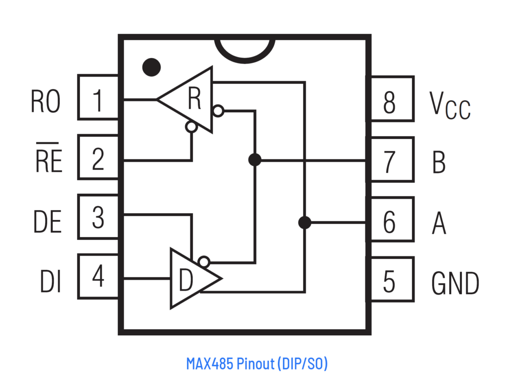
Truth Table
| Inputs | Outputs | |||
|---|---|---|---|---|
| RE | DE | DI | Y/A | Z/B |
| X | 1 | 1 | 1 | 0 |
| X | 1 | 0 | 0 | 1 |
| 0 | 0 | X | High-Z | High-Z |
| 1 | 0 | X | High-Z | High-Z |
| Inputs | Outputs | ||
|---|---|---|---|
| RE | DE | A-B | RO |
| 0 | 0 | > +0.2V | 1 |
| 0 | 0 | < -0.2V | 0 |
| 0 | 0 | Inputs Open | 1 |
| 1 | 0 | X | High-Z |
RS485 to TTL Module
There are a few types of MAX485 modules available in the market. One of them is a basic MAX485 circuit board with input and output pins for direct interfacing. In addition to the TX and RX signals, you also need to control the RE and DE pins.
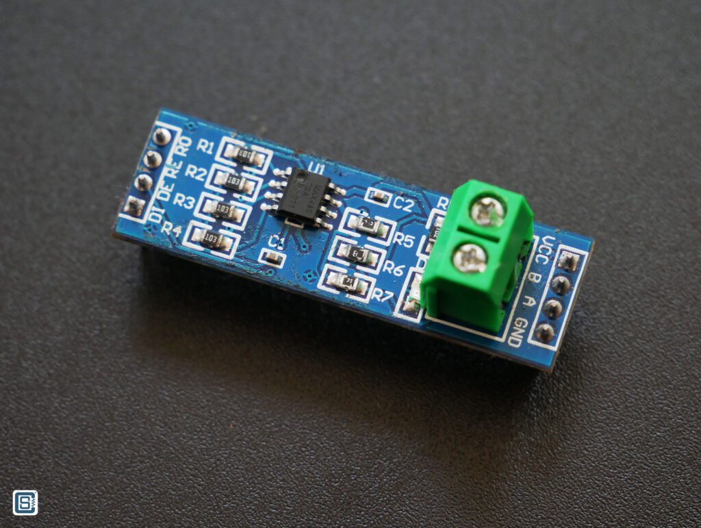

Another type is one that comes along with a CD4069 hex-inverter IC. CD4069 is a logic inverter IC with 6 input and 6 output pins. An inverter simply produces a complementary (opposite) output for an input applied. So if the input is HIGH then the output will be LOW and vice versa. The CD4069 on the module automatically drives the DE and RE pins of the MAX485 IC when you transmit or receive messages. This simplifies the operation and programming.

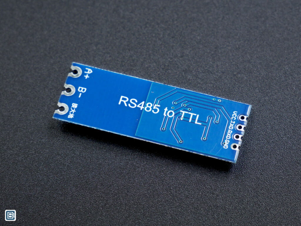
Pinout


Schematic
Below is the schematic of the module we have created by reverse engineering the module. We also found that many similar modules come with the IC numbers scrapped off to prevent reverse engineering. Duh! 🤥
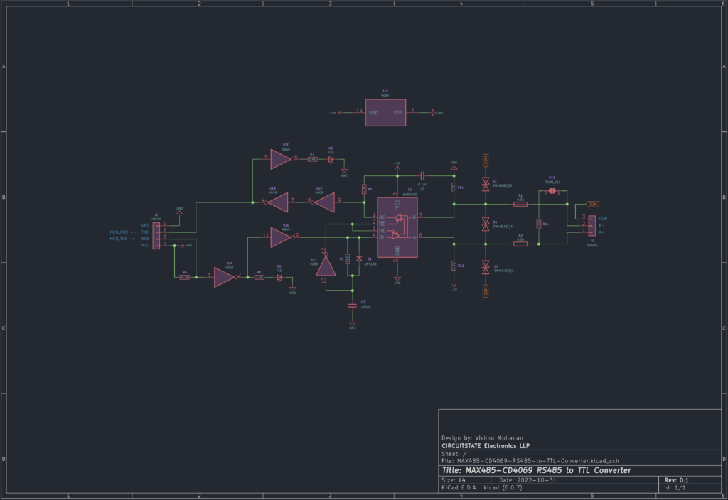
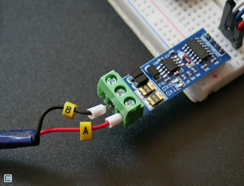
As you can see from the schematic, all of the inverters are used up for the automatic transmit and receive mode selection. A few of the component designators are the same as what you see on the board. On the RS-485 connector side, there are three pads for soldering the A and B signal wires and an optional COM (Common) line. The Chinese label on the PCB says something like “grounded” when we tried to use the Google Lens application for translating. But this must not confuse you. The COM pin is not meant to be connected to a supply ground or Earth. Instead, you can use the COM pin for connecting the shielding wires together providing a common potential along the long wire.
The board also has three TVS (Transient Voltage Suppression) diodes for protecting lines from spurious voltages. The diode used appears to be SMAJ6.8(C)A as per our investigation. In addition to the TVS diodes, there are two resettable SMD fuses with a value 1010 (the last 0 is a week code) written on them. The PTC fuse marking likely indicates a maximum current 0.3A. But we are not so sure. If you know it, please let us know.
The A line is pulled-up and B line is pulled down with the help of 4.7K resistors. They are used for failsafe biasing. It allows the differential lines to be at a determined state when all drivers are off. If you are using the module at either end of an RS-485 bus, then you can also enable the 120 Ohms termination resistor by shorting the pads marked as R13. Connecting this module to another RS-485 module is as we explained before. A connects to A and B connects to B on the other side.
On the input side of the module, we have four pins. VCC and GND should be used to supply a voltage of 5V. TXD pin where you should connect the RX pin of the microcontroller. Similarly, RXD pin of the module connects to the RX pin of the microcontroller. Since MAX485 is a half-duplex IC, either RXD or TXD pin will be active at a time.
The UART lines are active-low which means, the pins will be at HIGH level (+5V) when not active. When you transmit data through the RXD pin of the module, the pin will be made LOW. This signal is connected to U1A inverter which drives the TXD LED to indicate that you are transmitting. The output of U1A is connected to U1E which drives the DI pin of MAX485, making it transmit a logical 1. But the pins RE and DE pins also should be driven for transmit mode. This is accomplished by U1F. The capacitor C2 will remain charged through R5 when the RXD pin is in the idle state. U1F will keep the RE and DE pin LOW for receive mode. When you transmit a bit through the RXD line, the output of U1F becomes HIGH which automatically switches MAX485 to transmit mode. The capacitor C2 can now discharge through the diode D1.
The RO pin of MAX485 is pulled up by default. So the pin remains HIGH in idle condition. When you receive data bits from another transmitter, the line becomes LOW. This signal is passed through two inverters U1D and U1B to provide a LOW signal at the TXD pin. The U1C will also drive the RXD LED at this time indicating you are receiving data.
So that is how this particular module works. You can download the KiCad V6 schematic if you plan to design your own RS-485 board. Let’s see how we can use this module with popular microcontroller boards.
Interfacing
We are going to use two RS-485 modules and two ESP32 development boards for this test. You can use any microcontroller development board with a UART for this test such as Arduino Uno, ESP8266, STM32 Nucleo, or Raspberry Pi Pico. If your board doesn’t have a spare UART port you could still use the Arduino SoftwareSerial library.
Wiring
| ESP32 | RS-485 Module |
|---|---|
| 3V3 | VCC |
| GND | GND |
| GPIO 16 (RX2) | RXD |
| GPIO 17 (TX2) | TXD |
Unlike how you normally wire UART ports (TX to RX and RX to TX), we have to connect the RX pin of the microcontroller to the RXD pin of the RS-485 module and the TX pin to the TXD pin. This is because the RS-485 module is not a UART device itself, but a pass-through system only. We are using the RX2 and TX2 pins of the ESP32 because the other pins are reserved for other purposes such as programming the board.

Code
Following is the Arduino code we used for the ESP32 board for testing RS-485 communication.
#define PIN_RS485_RX 16
#define PIN_RS485_TX 17

void setup() {
  Serial.begin (115200);
  delay (1000);

  // Serial2.begin (115200, SERIAL_8N1, PIN_RS485_RX, PIN_RS485_TX);
  Serial2.begin (115200);
  delay (1000);

  Serial.println ("RS485-Test");

  delay (1000);
}

void loop() {
  if (Serial2.available()) {
    Serial.print ("Message RX: ");
    Serial.println (Serial2.readStringUntil ('\n'));
  }

  if (Serial.available()) {
    Serial.print ("Message TX: ");
    String msg = Serial.readStringUntil ('\n');
    Serial.println (msg);
    Serial2.print (msg);
  }

  // Serial2.println ("123");
  // delay (100);
}
We are using the default USB serial (Serial) for printing the sent and received messages. The Serial2 is the dedicated UART port we are using for sending and receiving RS-485 data. We begin both serial interfaces at 115200 bps baud rate. We are using the default UART configuration here. But if you need to change the UART configuration for a custom application, you can pass those parameters during the begin() call.
In the loop() function, we will continuously check if any of the serial ports have data received in them. If data is received on the RS-485 port, we will read and print the data to the USB serial. Similarly, if data is received on the USB serial port, it will be written to the RS-485 line. The RS-485 receiver at the other end can now receive this data. You can use any standard serial monitor application for sending and receiving data. We are using VS Code’s serial monitor here.

CSE_ArduinoRS485
CSE_ArduinoRS485 is an Arduino library from CIRCUITSTATE Electronics for implementing RS-485 communication on all Arduino-compatible microcontroller boards. It is a fork of the official ArduinoRS485 library from Arduino. We have added many improvements to it and removed many of the hardware dependencies. Unlike the official library, CSE_ArduinoRS485 supports both hardware and software serial (UART) interfaces. The open-source library is available on our GitHub and it is well documented on our RS-485 tutorial. You can check it out to learn more about the library.
Below is a sample code for printing incoming messages on a serial port used for RS-485. You need two serial ports for the demo. The code is written and tested on an ESP32 board, but you can adapt it to any Arduino-compatible board. For the RS-485 interface, we used the MAX485+CD4069 module. You first need to complete this test to make sure RS-485 is working with your board correctly.
//===================================================================================//

#include <Arduino.h>
#include <CSE_ArduinoRS485.h>

//===================================================================================//

#define PIN_RS485_RX        16
#define PIN_RS485_TX        17

#define PORT_USB            Serial
#define PORT_RS485          Serial2

//===================================================================================//
// Globals

// Create a new RS-485 port with (serial port, DE pin, RE pin, TX pin)
RS485Class RS485 (PORT_RS485, -1, -1, PIN_RS485_TX);

//===================================================================================//
// Forward declaration

void setup();
void loop();
void readRS485();

//===================================================================================//

void setup() {
  // Initialize default serial port
  PORT_USB.begin (115200);
  delay (1000);

  // Initialize the RS485 port manually
  PORT_RS485.begin (9600, SERIAL_8N1, PIN_RS485_RX, PIN_RS485_TX);

  // Initialize the RS485 object.
  RS485.begin();
  delay (1000);

  PORT_USB.println ("--- RS485 Test ---");
  delay (1000);
}

//===================================================================================//

void loop() {
  readRS485();

  // Get data from the USB port and send it to the RS485 port.
  if (PORT_USB.available()) {
    PORT_USB.print ("TX: ");
    String msg = PORT_USB.readStringUntil ('\n');
    PORT_USB.print (msg);
    RS485.print (msg);
  }

  delay (5);
}

//===================================================================================//
/**
 * @brief Read data from the RS485 port and print it to the USB port.
 *
 */
void readRS485() {
  if (RS485.available()) {
    // Read incoming message from the RS-485 port
    String msg = RS485.readString();

    // Print the message as a string
    PORT_USB.print ("RX String: ");
    PORT_USB.println (msg);

    // Print the message as decimal values
    PORT_USB.print ("RX Dec: ");
    for (int i = 0; i < msg.length(); i++) {
      PORT_USB.print (msg [i], DEC);
      PORT_USB.print (" ");
    }
    PORT_USB.println();

    // Print the message as hex values
    PORT_USB.print ("RX Hex: ");
    for (int i = 0; i < msg.length(); i++) {
      if (msg [i] < 0x10) PORT_USB.print ("0");
      PORT_USB.print (msg [i], HEX);
      PORT_USB.print (" ");
    }
    PORT_USB.println();
    PORT_USB.println();
  }
}

//===================================================================================//Debugging
Debugging RS-485 communication can be carried out with the help of an oscilloscope (CRO or DSO). You can measure the voltage between the A and B lines and check if they are within the required limits and correct polarities. If the A/B lines are swapped, you will still be able to send the signals but the receiver won’t be able to understand the data. You also need to make sure that both the sending and receiving ends agree to use the same UART configuration.
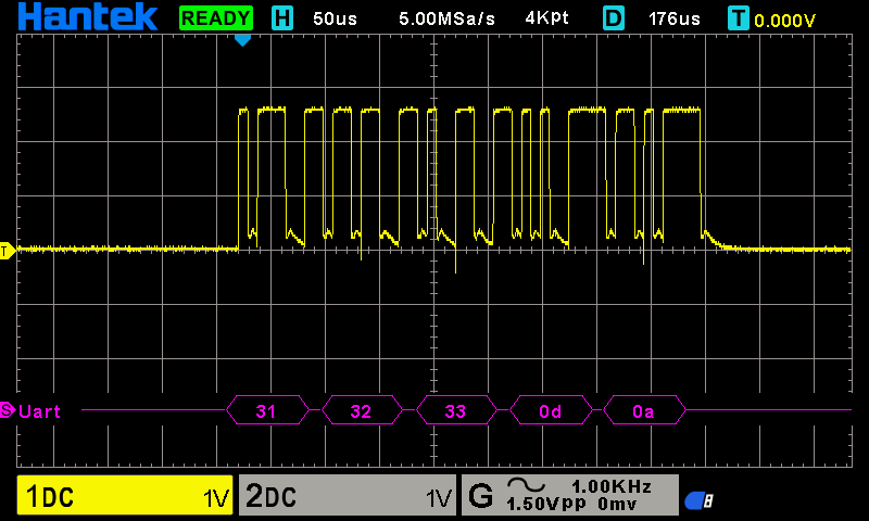
Some DSOs have the capability to decode UART signals. We used the Hantek DSO2D15 to probe the RS-485 communication lines and decode the data we are sending. We first set the trigger mode to UART with a baud rate of 115200 and trigger initiation at the start bit of the UART frame. So whenever the DSO captures a waveform that resembles the start condition of UART, it will capture the remaining series of waves as UART frame, decode the data and show it on the screen. You can this in action in the below screenshots.


| Hex | 0x31 | 0x32 | 0x33 | 0x0D | 0x0A |
|---|---|---|---|---|---|
| Char | 1 | 2 | 3 | CR | LF |
UART is an active-low bus and transmits LSB-first. For example, 0x31 is 00110001 in binary but the UART sends it as 10001100.
That’s everything for this tutorial. There is still a lot more to learn about RS-485 and its practical applications. But we hope we have been able to give you a good overview of the RS-485 communication standard and give you enough inspiration to use RS-485 for long-distance communication in your next project.
Links
- Original TIA/EIA-485 Standard Specification [PDF]
- RS-485 Serial Interface Explained – CUI Devices
- Explanation of Maxim RS-485 Features – Analog Devices
- RS485 Cabling – Why you need 3 wires for 2-wire RS485?
- Basics of RS-485 – Texas Instruments [PDF]
- RS-422 / RS-485 Industrial Standards
- What is RS-485 and how is it used in industrial control systems? – RealPars
- How do I wire RS485 devices? – Innon
- Wiring of RS485 Communications Networks – Schneider Electric
Short Link
- Short URL to this page – https://circuitstate.com/rs485arduino


Is it possible to use this code to read plc data using an esp32 and max485?
( i want to send the plc informations to the esp32)
Yes Nadhir, you can use this library for reading PLC data coming through an RS-485 interface. You just have to know the data types and their addresses.
Hi there, thanks for your excellent post and your re-engineering efforts. You use the board on the esp32 which runs on 3,3V. The RS485-Transceiver on your board is a MAX485ESA which seems not 3,3V compatible. Don’t you need some kind of level shifting?
You are right. The recommended supply voltage for the MAX485ESA is a 5V. But as you can see, it will still work with a supply of 3.3V, but with a lower output drive strength. For proper practical implementation, you have to either use 3.3V RS-485 drivers or use voltage translators.
The library didn’t work using SoftwareSerial on STM32F103C6T6 Bluepill low density.
Compiling library "CSE_ArduinoRS485"/home/luthfialhadi/.arduino15/packages/STMicroelectronics/tools/xpack-arm-none-eabi-gcc/13.2.1-1.1/bin/arm-none-eabi-g++ -mcpu=cortex-m3 -DVECT_TAB_OFFSET=0x0 -DUSE_HAL_DRIVER -DUSE_FULL_LL_DRIVER -mthumb @/tmp/arduino/sketches/B536F6C231545177D5D4645E530CC3AC/sketch/build.opt -c -Os -DNDEBUG -std=gnu++17 -ffunction-sections -fdata-sections -fno-threadsafe-statics --param max-inline-insns-single=500 -fno-rtti -fno-exceptions -fno-use-cxa-atexit -MMD -I/tmp/.arduinoIDE-unsaved2024724-2219-dylzfj.q43zs/RS485_Receiver -
…[Redacted]
Please create an issue at the GitHub repository. It is the best place for us to help you with such errors. Your compiler log has been redacted to keep the comment section clean.
Hi, fantastic tutorial. I have one doubt, TVS diode used in MAX485 CD4069 ttl module will work only when COM pin is connected, right?
Thank you. Since the TVS didoes are connected to the RS-485 bus side, they will work whenever the bus voltage exceeds the didoe ratings, regardless of whether the board is powered or not.
Thank you very much for your tutorial.
🙏