Reading Push-Buttons Through Polling : Learn Microcontroller with STM8S – Tutorial Part #6
In the last post, we learned how to use the GPIO’s output capability to drive an LED and blink it through a program. GPIO pins also supports different types of input functionalities. In this post, we will learn about the basic digital input functionality of GPIO pin of the STM8 microcontroller. To follow this tutorial, you will need a tactile push-button, a 1K Ohms through-hole resistor, a breadboard and a few jumper cables. If you missed the last part of this tutorial series, you can check it out below.
Blinking LED with Timer Interrupts : Learn Microcontroller with STM8S – Tutorial Part #5
Tutorial Series
- Learn the fundamentals of microcontrollers.
- Familiarize with a simple STM8S microcontroller.
- Install all the software tools and prepare your computer for programming and debugging microcontrollers.
- Get hands on experience with connecting your first microcontroller board and write a program for it.
- Learn the concepts of timers and interrupts in microcontrollers and blink an LED with what you learn.
- Learn how to make your microcontroller interact with the world by reading a push-button.
- Learn how to read a push-button using external interrupts without blocking critical code.
What You’ll Learn
- How does a tactile push-button work.
- How to read GPIOs using polling method.
Push-Buttons
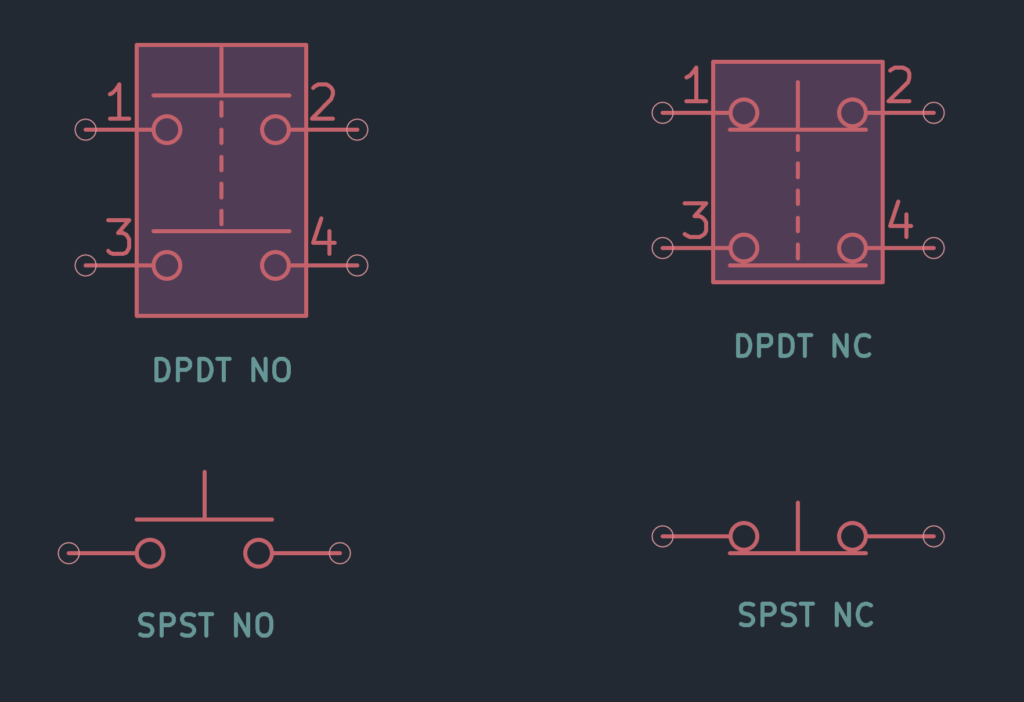
We had briefly shown you in the previous tutorial how you can interface a push-button to a microcontroller. Though they come in different sizes, shapes and configurations, push-buttons are simple mechanical devices which either close or break a circuit. The most common type is a tactile SPST (Single-Pole Single-Throw) one. Pole indicates how many inputs the switch can accept and Throw indicates the number of output pins. We will use a regular 6×6 mm SPST push-button in this tutorial and show how you can use the GPIO input feature of a microcontroller to read a push-button. Push-buttons are also called momentary switches because they close or open a circuit momentarily.
Active-Low and Active-High
There are two ways you can connect a push-button to the GPIO pin of a microcontroller. You can connect one end of the switch to GND and the other end to the GPIO pin with a pull-up resistor, as shown below.
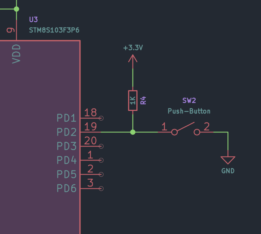
This configuration is generally called Active-Low since the pushed state of the push-button is indicated by a LOW state on the GPIO pin. The pull-up resistor keeps the GPIO from floating, and in a known state always. When you read the GPIO pin when the push-button is not pressed, you will always read a HIGH. When the button is pressed however, the state becomes LOW.
In the next configuration, one end of the push-button is connected to the VCC supply. The other end is connected to the GPIO pin with a pull-down resistor. This reverses the input logic. When the button is not pressed, the state of the GPIO pin will be LOW, and when it is pressed, it changes to HIGH. This configuration is called the Active-High.
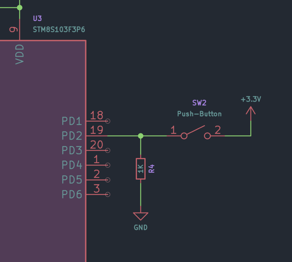
Whether to use the Active-Low or Active-High configuration is completely up to you. But the Active-Low configuration is more common since most microcontrollers come with internal pull-up resistors but not many with pull-down resistors.
Reading Methods
Reading a push-button means checking the state of the push-button so that we know when it is pressed. There are mainly two ways of reading push-buttons using GPIO pins – Polling and Interrupt.
Polling
In this method, you have to continuously read an input GPIO to read the state of the pin. This method is called Polling since you have to periodically poll the pin to read the state. The rate of polling is decided by the program. The problem with this method is that if the input state changes when you are not reading, you will miss the input change. If your microcontroller has to execute some code that takes a certain time to finish, it will not be able to read a GPIO pin at the same time. If you read the GPIO pin fast enough, this might not pose a problem, in which case polling is the simplest method to read a push-button with a microcontroller. We will demonstrate the polling method later in the code section.
Interrupt
Another method is to use interrupts. Yes, the same interrupts we used to blink LEDs. Interrupts are one of the most interesting features of a microcontroller. In the interrupt method, instead of reading the push-button repeatedly, we will wait for it to be pushed. But wait, does that mean we have to suspend all other tasks? No, we will use an ISR (Interrupt Service Routine) to respond to the interrupt from a GPIO pin when the push-button is pressed. That means, we can carry on any tasks as if nothing happened. When the push-button is pressed, a special interrupt will temporarily suspend the running task and read the push-button to read the state. This does not even require reading the push-button because we already know that it was pressed. That is an extra responsibility removed from the programmer. We will demonstrate the interrupt-based code in the next tutorial.
Wiring
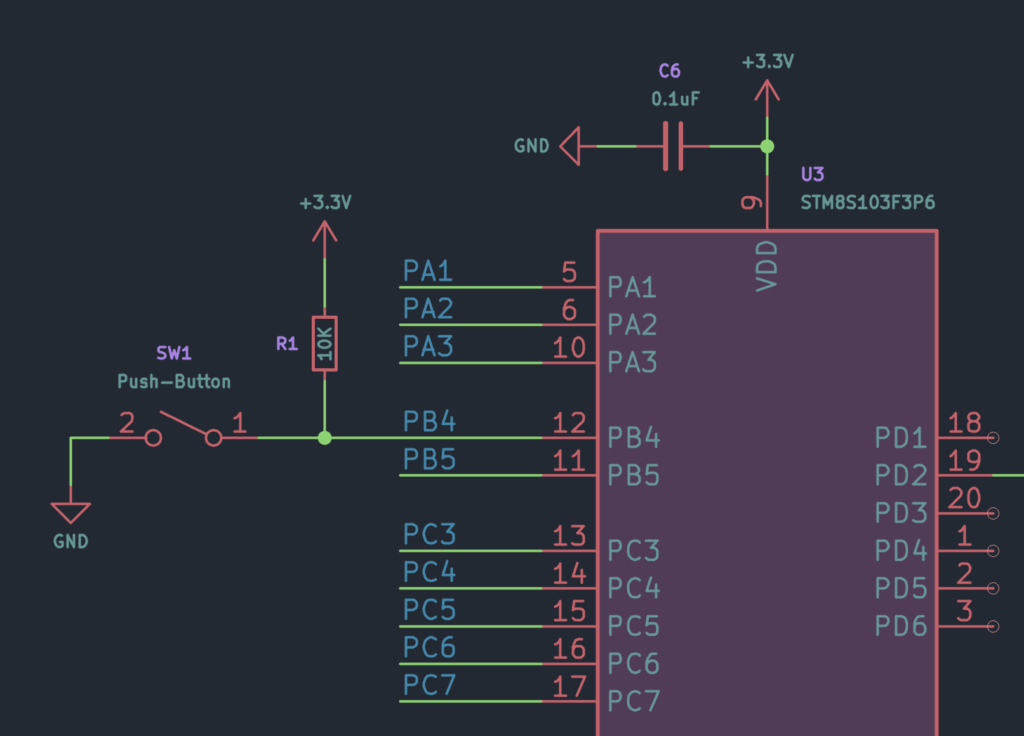
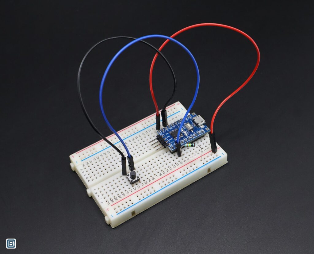
We are going to use PB4 GPIO pin to connect the push-button. You can use any other free GPIO pins. You just need to use the correct pin number in your code. For pull-up, we are using a 10K through-hole resistor. Since there is an LED already connected to the PB5 pin, we will use it for blinking. You can also connect an external LED to any other GPIO pin. We are using a small breadboard here to connect everything.
Code
Following is the polling-based code for reading a push-button. After reading the push-button, we will blink an LED. We can write a small algorithm to plan how to write the program.
- Configure the LED pin as a push-pull output.
- To keep the LED off initially, write
LOWto the pin. - Configure the push-button pin as an input with internal or external pull-up.
- Repeatedly check the state of the GPIO connected to the push-button.
- If the push-button is pressed, blink the LED two times.
- If the push-button is not pressed, keep reading the button and keep the LED off.
.stm8

;---------------------------------------------------------------------------------;

; STM8 Naken-ASM Assembly Program:
; LED blinking on a push-button press.
; Author: Vishnu Mohanan (@vishnumaiea)
; Version 0.1

;---------------------------------------------------------------------------------;

.include "stm8s103.inc"

F_CPU           EQU   16000000  ; CPU clock frequency, required by delay routines
DELAY           EQU   100       ; Blink interval in ms

; CLK_CKDIVR flags
HSIDIV_00       EQU   0x00      ; HSI prescaler: fHSI / 1
CPUDIV_000      EQU   0x00      ; CPU prescaler: fMASTER / 1

LED             EQU   5         ; LED pin index on Port B (B5)
BUTTON          EQU   4         ; Push-button pin on Port B (B4)

.org RAM_START                  ; Where variables are stored
counter:        .db   0x00

.org CODE_START                 ; Where the code starts

;---------------------------------------------------------------------------------;
; Main program body.

start:
    MOV     CLK_CKDIVR, #(HSIDIV_00 | CPUDIV_000)  ; clock setup

    BSET    PB_DDR, #LED        ; Set the LED pin as output
    BSET    PB_CR1, #LED        ; Set the LED pin as push-pull
    BSET    PB_ODR, #LED        ; Set the LED output to LOW initially

    BRES    PB_DDR, #BUTTON     ; Set the push-button pin as input
    BRES    PB_CR1, #BUTTON     ; Set the CR1 bit to 0 to disable the pull-up

;---------------------------------------------------------------------------------;
; This function continously read the button state and toggle the LED if the button is pressed.

loop:
    BTJT    PB_IDR, #BUTTON, skip   ; Check the input bit for the button and jump if it is True
    CALL    blink_led               ; Call the blink_led function
    skip:                           ; If the button is not pressed, program skips to here
    JP      loop                    ; loop forever

;---------------------------------------------------------------------------------;
; Function to blink the LED two times.

.func blink_led
    LD      A, #4
    LD      counter, A
    loop:   ; Example for a label with local scope
        LDW     X, #DELAY       ; Load the blink interval
        BCPL    PB_ODR, #LED    ; Toggle the LED pin
        CALL    delay_ms        ; Wait for the DELAY ms
        DEC     counter
        JRNE    loop
    RET
.endf

;---------------------------------------------------------------------------------;
; Function to create delays in multiple of a millisecond.

.func delay_ms
loop_ms:
    LDW     Y, #((F_CPU / 1000) / 3)    ; Set the inner loop to the equivalent of 1000 us

loop_cycles:
    DECW    Y                   ; Decrement the inner loop
    JRNE    loop_cycles         ; Loop until Y is zero
    DECW    X                   ; Decrement the number of milliseconds
    JRNE    loop_ms             ; Loop until X is zero
    RET
.endf

;---------------------------------------------------------------------------------;
; Interrupt vectors.

.org VECTORS_START
    INT     start       ; RESET handler, jump to the main program body

;---------------------------------------------------------------------------------;Uploading
We will upload the code and run it before explaining it. You can assemble the programs using the following command, just like we always do.
naken_asm main.asm -o main.hex -type hex -lAssembling the polling-based code generated the following log. We have 70 code bytes that need to be written to the flash memory and 2 data bytes that need to be written to the RAM.
PS D:\Code\Naken-ASM\STM8\Push-Button-Polling> naken_asm main.asm -o main.hex -type hex -l

naken_asm

Authors: Michael Kohn
         Joe Davisson
    Web: https://www.mikekohn.net/
  Email: mike@mikekohn.net
Version:

 Input file: main.asm
Output file: main.hex
  List file: main.lst

Pass 1...
Pass 2...

Program Info:
Include Paths: .
               /usr/local/share/naken_asm/include
               include
 Instructions: 24
   Code Bytes: 70
   Data Bytes: 2
  Low Address: 0x0000 (0)
High Address: 0x80c1 (32961)The assembler generated the following hex file.
:020000000000FE
:0480000082008080FA
:10808000350050C6721A5007721A5008721A5005FD
:1080900072195007721950087208500603CD80A358
:1080A000CC8098A604B700AE0064901A5005CD802D
:1080B000B63A0026F28190AE14D5905A26FC5A2684
:0280C000F58148
:00000001FF
If you now try to upload the hex file using the following command,
stm8flash -c stlinkv2 -p stm8s003f3 -w main.hexyou will get the following error.
PS D:\Code\Naken-ASM\STM8\Push-Button-Polling> stm8flash -c stlinkv2 -p stm8s003f3 -w main.hex
Determine FLASH area
libusb: error [init_device] device '\\.\USB#VID_1532&PID_0099&MI_03#6&3475DE72&0&0003' is no longer connected!
libusb: warning [force_hcd_device_descriptor] could not infer VID/PID of HCD hub from '\\.\ROOT#USB#0000#{3ABF6F2D-71C4-462A-8A92-1E6861E6AF27}'
libusb: warning [force_hcd_device_descriptor] could not infer VID/PID of HCD hub from '\\.\ROOT#USB#0000#{3ABF6F2D-71C4-462A-8A92-1E6861E6AF27}#UDE'
libusb: error [init_device] device '\\.\USB#VID_046D&PID_0825&MI_02#8&1DF2C811&0&0002' is no longer connected!
Due to its file extension (or lack thereof), "main.hex" is considered as INTEL HEX format!
Address 0000 is out of range at line 1There is obviously something wrong with what we are doing. The assembler did not give us any errors. So it is not an issue with the code. The programmer says “Address 0000 is out of range at line 1”. Let’s recall the function of a programmer. The STM8Flash is a programmer tool that communicates with a suitable hardware Debugger/Programmer and transfers the binary data to the memory of a microcontroller. The STM8Flash tool can only write to the Flash memory space (Code Space) of the microcontroller, and not the Data Space (RAM). Since we are using variables stored in the RAM to write our program, NakenASM also adds them to the hex file. In order to help the STM8Flash tool to write the hex file, we need to delete the first line from the hex file and save it. For example, after removing the first line from the hex file, it looks like the following.
:0480000082008080FA
:10808000350050C6721A5007721A5008721A5005FD
:1080900072195007721950087208500603CD80A358
:1080A000CC8098A604B700AE0064901A5005CD802D
:1080B000B63A0026F28190AE14D5905A26FC5A2684
:0280C000F58148
:00000001FF
After removing the first lines, you will be able to upload the file. After uploading, you can try pressing the push-button and see the LED blinks twice for every press. If you keep pressing the button, the LED will blink repeatedly.
Code Explained
Following is the first section of the program. Many of the lines here are already familiar to you. Because we need to blink the LED, we need the CPU frequency and delay parameters. We also need to configure the clock source correctly. The first four assignments take care of that.
F_CPU           EQU   16000000  ; CPU clock frequency, required by delay routines
DELAY           EQU   100       ; Blink interval in ms

; CLK_CKDIVR flags
HSIDIV_00       EQU   0x00      ; HSI prescaler: fHSI / 1
CPUDIV_000 EQU 0x00 ; CPU prescaler: fMASTER / 1We are going to use the Port B for both controlling the LED and reading the push-button. PB5 is connected to the LED and PB4 is connected to the push-button.
LED             EQU   5         ; LED pin index on Port B (B5)
BUTTON EQU 4 ; Push-button pin on Port B (B4)The next two lines are interesting. In order to blink the LED twice, we need to generate a delay four times. Two of the times, the LED will be ON and two of the times the LED will be OFF. For reasons that will become obvious to you later, we need to store a counter value in the RAM to achieve this. The value will be loaded with the number of delays we want to generate and decremented after each delay. The RAM (Data Space) of the STM8S microcontroller starts at 0x0000. RAM_START is a macro defined in the stm8s103.inc file so that we don’t have to always remember these values. It has the same value of 0x0000 for the specific variant of STM8S microcontroller we are using.
In order to create a variable, we need to give it a unique label. Here, we are naming it as counter. The .db indicates that counter is a byte variable, storing only one unsigned byte. The variable is initialized with a value of 0x00. Without initializing, the variable can return a random junk value when tried to read it.
.org RAM_START                  ; Where variables are stored
counter: .db 0x00.db is one of the many data types supported by NakenASM. Following is the complete list of types.
| Type | Description |
|---|---|
.ascii {text} | Insert ASCII chars at memory address (no NULL term) |
.asciiz {text} | Same as .ascii but NULL terminated |
.db {data bytes} | 8 bit data bytes |
.dw {data words} | 16 bit data bytes |
.dc.w {data words} | 16 bit data bytes |
.dl {data words} | 32 bit data bytes |
.dc.l {data words} | 32 bit data bytes |
.dc16 {data words} | 16 bit data bytes |
.dc32 {data words} | 32 bit data bytes |
.dc64 {data words} | 64 bit data bytes |
.dq {data words} | 32 bit floats |
.resb {data byte count} | Reserve {count} bytes |
.resw {data words count} | Reserve {count} 16 bit words |
.binfile “binarydata.bin” | Read in binary file and insert at memory address |
The next line sets the starting address of the Code Space (Flash Memory) using a macro instead of a hard coded value.
.org CODE_START ; Where the code startsIn the following line, we configure the clock.
start:
MOV CLK_CKDIVR, #(HSIDIV_00 | CPUDIV_000) ; clock setupThe following lines configure the LED pins. In the first line, we are using the BSET (Bit Set) instruction to set the 5th bit of the PB_DDR (Data Direction Register) to 1. This will make the PB5 pin to an output. In the next line, we can set the type of output to Push-Pull by writing a 1 to the PB_CR1 register. In the last line, we can set the LED turned off initially, by writing a 1 to the PB_ODR (Output Data Register).
BSET    PB_DDR, #LED        ; Set the LED pin as output
BSET    PB_CR1, #LED        ; Set the LED pin as push-pull
BSET PB_ODR, #LED ; Set the LED output to LOW initiallyNext, we need to configure the push-button pin PB4. We just need to set the pin as an input and disable the internal pull-up. If you do not want to use an external pull-up resistor, simply use the BSET instruction instead of BRES.
BRES    PB_DDR, #BUTTON     ; Set the push-button pin as input
BRES PB_CR1, #BUTTON ; Set the CR1 bit to 0 to disable the pull-upBTJT
That is all the configuration we have to do. Next, we can go to our main loop function. The first line have a new instruction BTJT. It stands for Bit Test and Jump if True. It accepts three parameters in the following way.
BTJT dst, #pos, reldst is the destination byte and #pos (immediate value) is the bit position in the destination byte. The BTJT checks the specified bit at the destination byte, and if it is 1 (true) jumps to the relative memory location specified by rel.
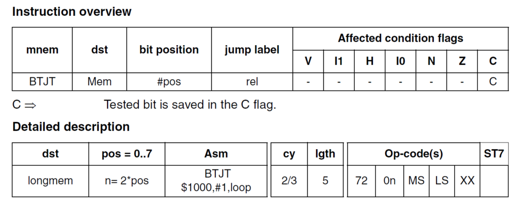
Here, our destination byte is the PB_IDR register. When the state of a pin HIGH, the register will hold a 1 at that bit position. When the pin state is LOW, we can read a 0 from the bit position. Since our push-button is active-low, we can read a 0 when the push-button is pressed. The bit position to check is, obviously, the pin where the push-button is connected. The last parameter skip is a relative jump label. The BTJT instruction checks if the bit and jumps to the skip label if it is true. If it is not true, the next instruction is executed. When the push-button is not pressed, the PB_IDR register will contain 1 at the 4th bit position, because of the pull-up. The instruction evaluates this as true and jumps to the skip label. The instruction followed by that label is a JP instruction that jumps back to the start of the program. So as long as the push-button is not pressed, the line 48 is never executed.
But when we press the button, BTJT evaluates to false, and instead of skipping, the next instruction will be executed. CALL instruction calls the blink_led function to blink the LED two times. After that, the program starts from the beginning due to the JP instruction.
loop:
    BTJT    PB_IDR, #BUTTON, skip   ; Check the input bit for the button and jump if it is True
    CALL    blink_led               ; Call the blink_led function
    skip:                           ; If the button is not pressed, program skips to here
JP loop ; loop foreverNext, we can look at the blink_led function. If you remember our first LED Blink program, we loaded the X register with a delay value and called the delay_ms function to create delays between the two states of the LED. In this case, however, we can not use the X register to load how many times we want to blink the LED. The X and Y registers will already be used for the delay functions. Therefore, we need to store the number of times we need toggle the LED pin state has to be stored somewhere else. This is what we are using the counter variable for.
; Function to blink the LED two times.

.func blink_led
    LD      A, #4
    LD      counter, A
    loop:   ; Example for a label with local scope
        LDW     X, #DELAY       ; Load the blink interval
        BCPL    PB_ODR, #LED    ; Toggle the LED pin
        CALL    delay_ms        ; Wait for the DELAY ms
        DEC     counter
        JRNE    loop
    RET
.endfLD
We first load the A (Accumulator) register with the number of times we need to toggle the LED pin. In order to turn on the LED two times we need to toggle the state four times. So we load A with an immediate value of 4. Next, we can load the counter variable with the value in the A register.
The instruction LD is used to load the A register with an immediate value. We are using this instruction for the first time. Unlike the LDW instruction we used before, LD only loads a single byte. Otherwise, the behaviour of the two instructions is the same.
LD dst, src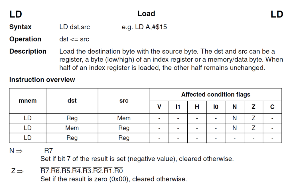
LD instruction overviewThe dst and src can be a register, a byte (low/high) of an index register or a memory/data byte. When half of an index register is loaded, the other half remains unchanged.
DEC
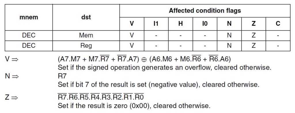
The lines coming after that is the same as our Blink program, except the DEC instruction. It decrements the counter variable by 1. After each time the LED is toggled, the counter variable is decremented. Since the DEC instruction affects the CPU status flags, the next instruction JRNE checks if the operation produced a 0 result. If the counter variable is still not 0, it will jump to the loop label. When the counter variable becomes 0, JRNE skips the instruction and returns from the function. By this time, we would have blinked the LED two times and returned to the main program. If you want to blink the LED more time, you just need to change immediate value of #4.
The delay_ms function is the same as we used in the previous Blink example. So we won’t explain that again. The program ends with the following lines. Instead of explicitly adding the vector start address of 0x8000, we are using a macro VECTORS_START.
; Interrupt vectors.

.org VECTORS_START
INT start ; RESET handler, jump to the main program bodyThe DEC instruction is similar to the DECW instruction we have used before. Instead of decrementing a word, DEC decrements a single byte and update the status flags.
In the next part, we will learn how to read the push-button through the interrupt method and how to overcome the limitations of the polling method. Check out the next tutorial below.
Reading Push-Buttons Through Interrupt : Learn Microcontroller with STM8S – Tutorial Part #7
Links
- What is A Microcontroller? : Learn Microcontroller with STM8S – Tutorial Part #1 – CIRCUITSTATE Electronics
- NakenASM – Official Website
- NakenASM – GitHub
- STM8 Assembler Playground
- STM8S Series – Official Product Page
- STM8S103F3 Datasheet [PDF]
- AN2752 – Getting Started with STM8S and STM8AF Microcontrollers [PDF]
- PM0044 – STM8 CPU Programming Manual [PDF]
- RM0016 – STM8S and STM8AF Series 8-Bit Microcontrollers [PDF]
- STM8 Product Lineup [PDF]
Short Link
- A short URL to this page – https://www.circuitstate.com/stm8readpbpolling


