Interfacing RA-01/RA-02 SX1278 LoRa Modules with ESP32 using Arduino
Learn how to interface RA-01 or RA-02 SX1278-based LoRa modules from Ai-Thinker with ESP32 using Arduino. LoRa can add long range and low-power wireless communication capability to your projects.

One of the things that fascinated me when I was a child was how radio communication worked. I wondered about how radio-controlled toy cars work without any wires. It was just magic in plain sight for me as a kid. I tried to replicate their functions in childish ways but never got them to work, except for making a speaker made of copper foils respond to sparking created by shorting large voltages, wirelessly (equivalent to a spark gap transmitter). It worked because electrical arcing can create radio waves in a broad spectrum of electromagnetic frequencies including the light we see as flashes. These radio waves can be picked up by other sensitive devices that are either deliberately or otherwise tuned to receive those signals. Fast forward to today, we are constantly engulfed by radio waves carrying information that we can’t perceive naturally. The cellular phones we use, Wi-Fi, Bluetooth, GPS, and much more work based on the same principle of sending and receiving radio waves.
With the advances in science and technology, the ways we use the radio spectrum have become smarter, and devices have become smaller and more efficient. Today, if you wanted to build a remote controller or some device to send a text message wirelessly, there are many handy ways to do that without a complete degree in electrical engineering. If you happen to own an Arduino board you can easily interface it with a variety of wireless communication modules you can buy from the open market and make them talk in a few minutes. One of the terms you will stumble upon while searching for such modules is LoRa, which actually stands for Long Range. LoRa is a proprietary and patented radio communication technique developed by a company called Cycleo but is now maintained by Semtech. LoRa is one of the many LPWAN technologies out there, where LPWAN stands for Low Power Wide Area Network. It is a type of communication network that consists of low-power radio transmitters, receivers, or dual-function transceivers, communicating within a span of a few kilometers.
Today we will check out the RA-01 or RA-02 LoRa communication modules based on Semtech’s SX1278 LoRa chip. The modules are produced Ai-Thinker and we will see how you can interface them with the popular ESP32 DevKit board using the Arduino platform. Thanks to smart folks around the globe, a lot of the work has been already done for us and we just need to put them together.
We can develop embedded firmware for you
CIRCUITSTATE can develop embedded firmware for any microcontroller/microprocessor including 8051, PIC, AVR, ARM, STM32, ESP32, and RISC-V using industry-leading SDKs, frameworks, and tools. Contact us today to share your requirements.

LoRa PHY
Modulation
The basic principle of radio communication is not different from how we use sound to communicate. We use the air as the medium to propagate sound as pressure waves. These waves travel from one location to another carrying information along with them. By modulating the sound in different frequencies and amplitudes, we can use it as a medium of communication. Similarly, radio communication uses waves, not sound waves but electromagnetic (EM) waves in the Radio Frequency (RF) spectrum to carry information. A radio transmitter can generate electromagnetic waves at specific frequencies in the RF range. This is usually accomplished by an RF oscillator circuit that produces electric currents that oscillate at high frequencies. When we feed this high-frequency electric current to a suitable antenna, the antenna can convert the oscillations to electromagnetic waves radiating from it. We will modulate this carrier with a baseband signal that carries the information we want to convey. If we place another antenna some distance away, that is also tuned to the same RF frequency, it can pick up EM waves and convert them to an equivalent electric current on a conductor. The electrical signal can be converted back to its original form through the demodulation process. The unmodulated RF wave with no information is called a carrier signal and the signal that is used to modulate the carrier is called a baseband signal.
When the information signal is analog, we can perform three types of modulation – Amplitude Modulation (AM), Frequency Modulation (FM), or Phase Modulation (PM). But when the information signal is digital, we can have three different modulations called keying, which are Frequency Shift Keying (FSK), Amplitude Shift Keying (ASK), and Phase Shift Keying (PSK). There are other complex modulation techniques that use combinations of different modulation schemes.
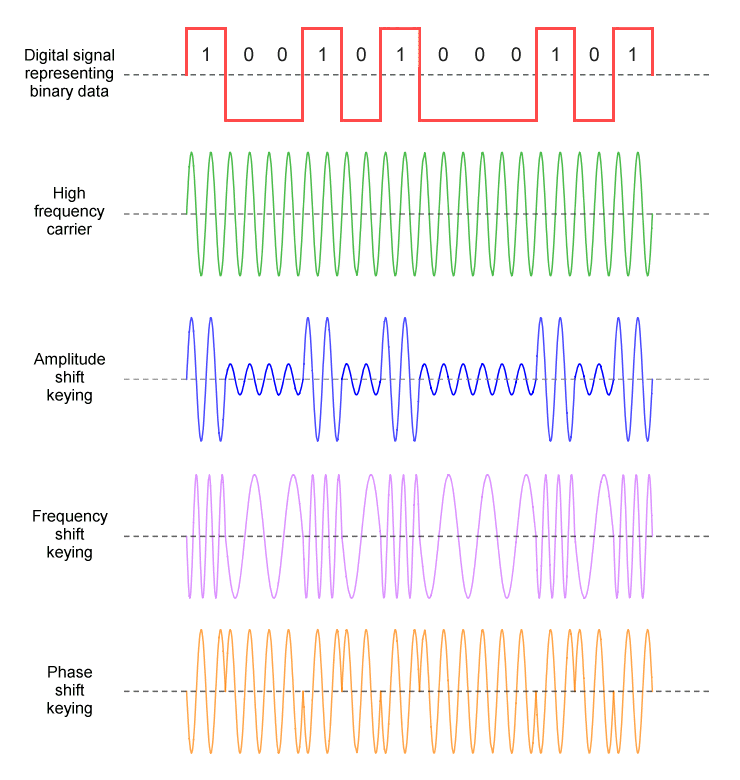
LoRa also uses an RF carrier signal (electromagnetic sine wave) for carrying digital baseband signals. But instead of the regular AM or FM modulation schemes, LoRa uses a Chirp-based modulation technique which is a type of FM/PM. A Chirp is a linear sweep of frequencies. Not only LoRa is Chirp-based, but it also uses the Spread Spectrum techniques to reduce interferences, which together are called Chirp Spread Spectrum (CSS). LoRa is only a description of the physical layer (PHY) which describes how the RF wave should be generated, how it should be modulated etc. The communication protocol and network architecture are defined by the LoRaWAN protocol. You can read a little more about how LoRa modulation works here.

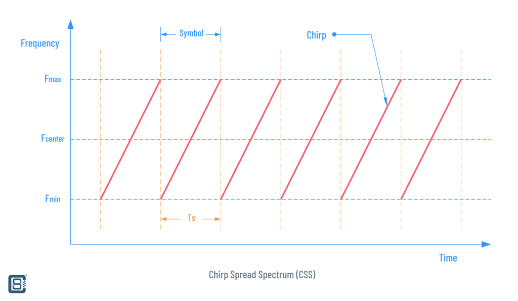
A chirp is a linear sweep of frequencies, increasing from Fmin to Fmax (up-chirp) or decreasing from Fmax to Fmin (down-chirp). The difference between Fmin and Fmax is the bandwidth (BW).
When using modulation for communication, we aim for getting the best data rate, a longer range, and fewer errors. But all three can not be attained at their best simultaneously. Practically, we will have to make some compromises and find an optimum value for each.
Each chirp can be considered a symbol. The number of symbols is therefore the number of chirps (either up or down) we are sending every second and it is called the symbol rate or chirp rate. The symbol rate can be varied by simply changing the time it takes to sweep the frequencies. In a graph, this will correspond to the slope of the chirp.
Now we can divide a single symbol or chirp into smaller frequency units and use them for encoding our data. A subdivision of a symbol is called a chip (yes, chip, and not chirp). But unlike you would expect, the chip division is in the frequency domain rather than the time domain. So a chip is expressed in Hz instead of a time period. A chip simply tells where to start the frequency sweep. How many chips we can have for every symbol is determined by a parameter called Spreading Factor (SF). SF is simply the number of bits (0 or 1) we can encode in a single symbol/chirp. The number of chips for an SF is calculated as,
Number of Chips = 2SF
Suppose we are only using up-chirps for encoding data. If the SF = 1, that means a symbol can only encode a single bit that can carry one of the two states, either 0 or 1. We will divide the BW into two chips and start sweeping from either Fmin or Fcenter. Starting sweeping from Fmax is equivalent to starting it from Fmin. Also, all sweeps are circular or cyclic in nature, which means we have to continue the sweep from where the previous sweep ended, for a single symbol period. This is illustrated below.
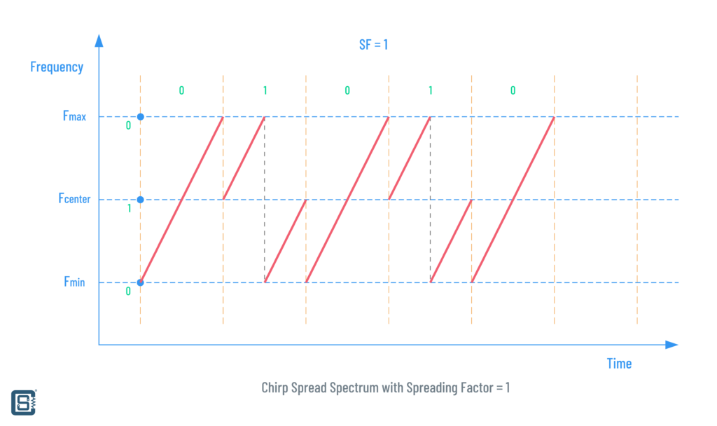
As you can see, for encoding binary 0 we do a continuous sweep from Fmin to Fmax. But for encoding binary 1, we sweep from Fcenter to Fmax. But since the symbol period would not have ended at that point, we need to cyclically shift it and start a new sweep from Fmin to Fcenter. Since SF = 1, we can only have those two states. But this is actually a waste of precious bandwidth. We can utilize a symbol better than that by increasing the SF. For example, if the SF = 2, then a single symbol can encode 22 = 4 states or chips as illustrated below.
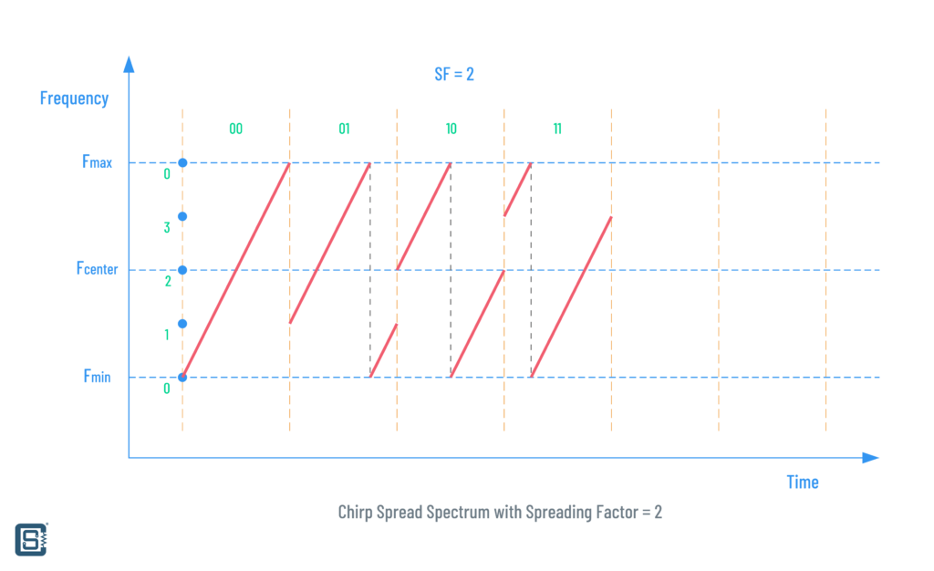
As you can see there are four frequency values we can start each sweep from. The positions are labeled from 0 to 3 indicating the 4 states. In the first symbol, we start sweep from 0 and end it at Fmax. It represents the symbol 00 (decimal 0). For 01 (decimal 1), we start the sweep from position 1 to Fmax. But since we still have the symbol period remaining, we start a new sweep from Fmin again, resulting in a new symbol 01. Similarly, we have 10 and 11, starting and ending at different frequencies and representing values 2 and 3 respectively. This is basically how the modulation of digital data in a CSS system works.
Now let’s talk about some rates. We already know that an unmodulated chirp takes up the entire bandwidth as either an up-chirp or down-chirp. The rate at which the frequencies are swept is called the Chirp Rate. If you look at the graphs, the chirp rate is equal to the first derivative (slope) of the chirp. The faster a chirp is, the steeper it will look. So what values of chirp rate are optimum? Chirp rate is calculated using the SF we need and it is calculated as the following.
Chirp Rate Rc = BW / 2SF
LoRa uses SF values from 7 to 12. That means each symbol must carry 7 bits minimum and up to 12 bits at a maximum. The value of SF can be chosen based on the range, data rate, and the type of terrain among other things. For example, if the BW = 125 KHz and SF = 7, then
Chirp Rate Rc = 125000 / 27
              = 125000 / 128
              = 976.5625
              ≈ 977 Chirps/s
Since we know that a chirp is equal to a symbol, the chirp rate is also the Symbol Rate of a CSS modulation. If we increase the SF to 12 for the same bandwidth, that will decrease the symbol rate.
Chirp Rate Rc = 125000 / 212
              = 125000 / 4096
              = 30.517
              ≈ 31 Chirps/s
That is significantly less than the symbol rate we got with SF = 7. The advantage of using a higher SF is that the signal will remain in the air for a longer period of time and therefore the receiver can better differentiate the LoRa signal from noise. But the disadvantage is that it takes more power to transmit a higher SF signal. See the illustration below and observe how changing SF affects the chirp rate. One cool thing about spreading factor is that multiple transmitters can use different SF and the same frequency channel to send data at the same time.

Now, what about the data rate? How much data we can send for each value of SF? Since SF determines both the chip count and the symbol rate, we can calculate the data rate as below.
Data Rate Rb = SF * (BW / 2SF) * (4 / (4 + CR))

Rb = bits/second
BW = Bandwidth in Hz
SF = Spreading Factor (7-12)
CR = Coding Rate (1-4)
Data Rate (DR) is specified in bits/second. Coding Rate (CR) represents the actual amount of bits that carry information. That is because not all bits are used to represent data. Instead, some bits are used to indicate other events such as a preamble, start position, end position, error correction data etc., just like we have extra bits in a UART communication. Increasing CR will decrease the actual data rate but reduces errors. Let’s try SF = 7 for a bandwidth of 125 KHz and coding rate 1.
Data Rate Rb = SF * (BW / 2SF) * (4 / (4 + CR))
             = 7 * (125000 / 27) * (4 / (4 + 1))
             = 5468.75 bits/s
That’s around 5.5 kbps of data transfer. The below table has a few more combinations of SF and BW.
| SF | BW | Data Rate (bps) | |
|---|---|---|---|
| 12 | 125 kHz | 250 | |
| 11 | 125 kHz | 440 | |
| 10 | 125 kHz | 980 | |
| 9 | 125 kHz | 1760 | |
| 8 | 125 kHz | 3125 | |
| 7 | 125 kHz | 5470 | |
| 7 | 250 kHz | 11000 |
| Coding Rate (CR) | CR = (4 / (4 + CR)) | Information bits for SF = 8 |
|---|---|---|
| 1 | 4 / 5 | 6.4 |
| 2 | 4 / 6 | 5.3 |
| 3 | 4 / 7 | 4.5 |
| 4 | 4 / 8 | 4.0 |
Different configurations of SF and BW yield different throughput and sensitivity characteristics. As said earlier, a high SF will result in a low data rate for a particular BW. But at the same time, it will increase the time period each bit is on the air. When a bit remains for a longer period in the air, it increases the energy of that bit and therefore improves the Signal to Noise (S/N) ratio. With a better S/N, even a device with lower sensitivity can receive the signal reliably. Or in other words, increased range. Deciding the LoRa parameters is highly application dependant and you can find more information on it in the LoRaWAN Regional Parameters document published by the LoRa Alliance. Also, there are many online calculators to find LoRa parameters such as this one.
Packet Format
Since LoRa is a patented technology, Semtech is not completely open about the itsy-bitsy details of LoRa. So many things are understood by reverse engineering and inference. For that reason, you will find so much confusing and partial or even conflicting information about LoRa on the internet. We will try to make sense of everything as best as we could.
LoRa uses two types of packet formats, one called Explicit Header Mode and another Implicit Header Mode. In explicit mode, the length of the payload, coding rate, and the presence of CRC (Cyclic Redundancy Check) code will be explicitly added to the data packet under a section called Header. This allows the transmitter to use a variable length payload and any receiving node can easily read the parameters directly from the packet. The LoRa explicit packet format is shown below.

- Preamble – The Preamble is a sequence of bits that helps to train or sync any receiver trying to get the packet. The preamble has a minimum length of 8.25 symbols (Ts). A preamble consists of the following parts.
- Variable Preamble – This is a sequence of unmodulated up-chirps. The chirp count can be programmed from 4 to 65535.
- Sync Word – Synchronization Word consists of 2 symbols. A receiver can use the sync word to detect LoRa networks by checking the sync word with a preset value. This value is programmable.
- SFD – Start Frame Delimiter acts as the end of the preamble. It consists of 2.25 down-chirp symbols.
- Header – This part is only present in explicit data packets. The header is always sent at a CR of 4 (4/8) to increase robustness. It is 20 bits long and contains the following parts.
- Payload Length – This tells how many bytes of data are there in the Payload part of the packet. The value can be from 1 to 255, but not 0. This field is 8 bits long.
- Payload CR – This is the coding rate for the payload and the accompanying CRC values. This is programmable from 1 – 4. This field is 3 bits long.
- Has CRC? – This is a 1-bit field that indicates whether the packet has a payload CRC associated with it. The CRC check can be skipped or not skipped based on the value of this field.
- Header CRC – This is a checksum for the header section itself. A receiver can ignore a packet with a bad header.
- Variable Payload – This is a variable-length data payload. The length is determined by the length value specified in the header. The maximum length is 255 bytes.
- Payload CRC – This is a 2-byte checksum value for just the data payload. This is an optional field determined by the value in the header section.
In the implicit mode, the header section is removed altogether. Instead, the lengths of the payload and CRC are fixed. This means a transmitter using an implicit packet should make sure that the receivers are also configured to read the same lengths or use the same configuration. By removing the header section, the implicit mode saves some data bandwidth.
Duty Cycle
When LoRa data is sent through any frequencies, it takes a certain of time to completely reach a receiver. This is called Time on Air (ToA) or Dwell Time. This time is determined by many parameters such as SF. Most regions have duty cycle limitations for LoRa. The duty cycle simply refers to the proportion of the time span you can transmit through a frequency channel. For example, European regions have a duty cycle limitation of 0.1 to 1% every day for a channel. Check your local regulations to learn more about regional limitations – LoRaWAN Regional Parameters. LoRa band used in India (IN865-867) does not have duty cycle or dwell time limitations as of now.
Frequency
LoRa devices are mostly dual-function, able to transmit (TX) and receive (RX) LoRa signals. That makes them transceivers (TRX). The frequency bands used by a LoRa transceiver can vary depending on the region. This is because the RF spectrum is a natural resource that is accessible by everyone and so countries have different rules to regulate their use. The radio frequency bands LoRa is designed to work fall under the ISM (Industrial Scientific Medical) category of frequencies. They are usually license-free bands that you can use without paying any fee or getting a license. But this does not have to be the case always or everywhere. You need to check with your country’s official entity that manages these kinds of things. For India, it is the Department of Telecommunications and other entities under it such as WPC (Wireless Planning and Coordination wing). You can find a list of frequency planning by various countries here.
| Europe | North America | China | Korea | Japan | India* | |
|---|---|---|---|---|---|---|
| Frequency Band | 867-869M Hz | 902-928 MHz | 470-510 MHz | 920-925 MHz | 920-925 MHz | 865-867 MHz |
| Channels | 10 | 64 + 8 + 8 | ||||
| Channel BW Up | 125/250 kHz | 125/500 kHz | 200 kHz | |||
| Channel BW Down | 125 kHz | 500 kHz | 200 kHz | |||
| TX Power Up | +14 dBm | +20 dBm typical (+30 dBm allowed) | Max +30 dBm | |||
| TX Power Down | +14 dBm | +27 dBm | ||||
| SF Up | 7-12 | 7-10 | 7-12 | |||
| Data rate | 250 bps – 50 kbps | 980 bps – 21.9 kpbs | 250 bps – 50 kbps | |||
| Link Budget Up | 155 dB | 154 dB | ||||
| Link Budget Down | 155 dB | 157 dB |
India officially delicensed the 865-867 MHz radio spectrum for public use on September 2020. But the document only mentions RFID applications and not LoRa or other use cases. So India as of now doesn’t have properly laid out frequency plans for LoRa communication. Luckily, that also means we can use the spectrum however we like. Notice that the spectrum is 1 MHz less than that of typically supported 865-869 MHz. The maximum bandwidth allowed in the 865-867 MHz band is 200 kHz. LoRaWAN only uses a maximum bandwidth of 125 kHz in the India region. The maximum transmit power is 1W (+30 dBm) with an effective radiated power (ERP) of 4 Watts.
If you want an example of a LoRa product, the iM880B-L is a LoRaWAN module certified for use in India. The 433-434 MHz band is also license-free in India but the bandwidth is limited to 10 kHz and the maximum transmit power (ERP) to 1 mW. You can read more about unlicensed radio bands in India here. The below table shows a list of data rates specified for LoRaWAN in India.
| Data Rate | Configuration | Indicative physical bit rate [bit/s] |
|---|---|---|
| 0 | LoRa: SF12 / 125 kHz | 250 |
| 1 | LoRa: SF11 / 125 kHz | 440 |
| 2 | LoRa: SF10 / 125 kHz | 980 |
| 3 | LoRa: SF9 / 125 kHz | 1760 |
| 4 | LoRa: SF8 / 125 kHz | 3125 |
| 5 | LoRa: SF7 / 125 kHz | 5470 |
| 6 | RFU | RFU |
| 7 | FSK: 50 kbps | 50000 |
| 8 – 14 | RFU | |
| 15 | Defined in LoRaWAN42 |
The LoRa frequency channels can be freely attributed by the operator for the India region. LoRaWAN also specifies three default channels that all transceivers must implement. If you use plain LoRa communication, try to use different channels for your application.
| Modulation | Bandwidth (kHz) | Channel Frequency (MHz) | FSK Bitrate or LoRa DR / Bitrate | # of Channels |
|---|---|---|---|---|
| LoRa | 125 | 865.0625, 865.4025, 865.985 | DR0 to DR5 / 0.3-5 kbps | 3 |
Power & Range
The maximum distance you can carry out LoRa communication depends on many factors. There is no one parameter that tells you the range you are going to get. Transmit power is usually regarded as the simplest parameter we can control. The more power we are transmitting, the higher the expected range. But that doesn’t have to be the case always. Typically, LoRa applications are designed to be able to communicate within a range of 5 to 10 kilometers. The range of a LoRa network can be extended to any length using repeater gateways and other means. The following are a few considerations to estimate or improve the working range of LoRa.
- Transmit Power – Electromagnetic waves get attenuated by the natural spreading of it governed by the inverse-square law of physics. Attenuation also happens due to absorption, dispersion, and reflection among others. So increasing the power (amplitude) of RF waves enables them to travel for a longer distance.
- Visibility– It doesn’t matter how powerful your transmission is if it is directed in the wrong direction! Having a Line of Sight (LOS) between a transmitter and receiver means, the receiver has a better chance of picking up your transmission with fewer errors. So make sure there are not many things blocking the LOS between your devices.
- Antenna – The type of antenna can make a day/night difference for RF communication. Choosing the right antenna for the right frequency, terrain, directivity, and sensitivity is very important. A properly tuned and placed antenna can pick up a weak signal and with a good LNA (Low Noise Amplifier) can continue communicating even in challenging situations.
Below is a table of expected ranges for different spreading factors. Also check out this post from Piotr Daniłowski where he experiment with different types of antenna for LoRa.
| Spreading Factor (For UL at 125 KHz) | Bit Rate | Range (Depends on Terrain) | Time on Air for an 11-byte payload |
|---|---|---|---|
| SF10 | 980 bps | 8 km | 371 ms |
| SF9 | 1760 bps | 6 km | 185 ms |
| SF8 | 3125 bps | 4 km | 103 ms |
| SF7 | 5470 bps | 2 km | 61 ms |
Applications
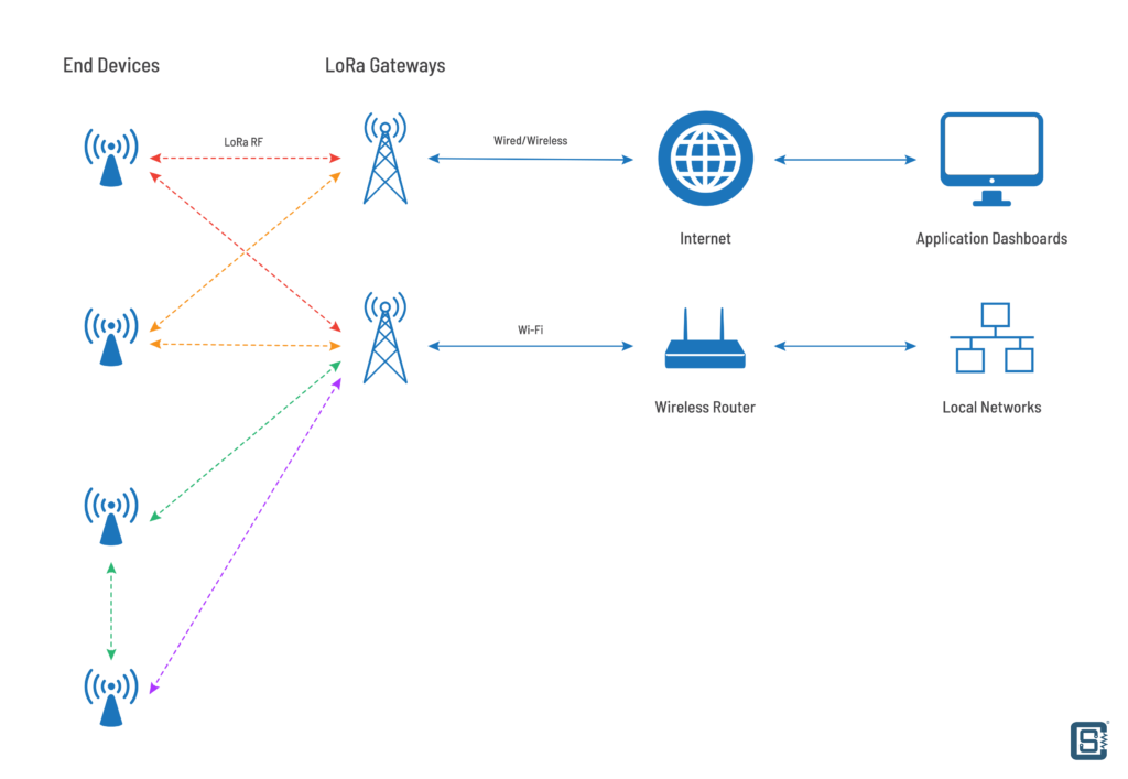
LoRa is designed to be low-power, long-range, reliable, and low-rate. It allows point-to-point wireless communication between devices (called nodes) that are battery-powered and spread across a large area. The data rate or bandwidth requirements of such devices will be small because they only have a handful of data at a time to transmit. Such applications include sensor networks that monitor conditions in the field and send that data back to a server. A LoRa network can have different types of topologies depending on how each node (device) is communicating. Usually, there will be a LoRa gateway, a device that receives data from all other transmitting nodes and send the data to some other network such as the internet. A protocol suite such as LoRaWAN is required to manage the devices and communication in a LoRa network. LoRa gateways can then connect to the internet or local networks via wired or wireless connections. Real-time data can then be sent to user applications or to a database.
SX1278
SX1276/77/78/79 are a series of LoRa PHY transceivers from Semtech. Available in QFN-28 SMD packages, they come with an integrated RF PA (Power Amplifier) with a maximum of +20 dBm (100 mW) output power and up to -148 dBm receive sensitivity. There are a few differences between the variants which are listed below.
| Part Number | Frequency Range | Spreading Factor | Bandwidth | Effective Bitrate | Est. Sensitivity |
|---|---|---|---|---|---|
| SX1276 | 137 – 1020 MHz | 6-12 | 7.8 – 500 kHz | 0.018 – 37.5 kbps | -111 to -148 dBm |
| SX1277 | 137 – 1020 MHz | 6-9 | 7.8 – 500 kHz | 0.11 – 37.5 kbps | -111 to -139 dBm |
| SX1278 | 137 – 525 MHz | 6-12 | 7.8 – 500 kHz | 0.018 – 37.5 kbps | -111 to -148 dBm |
| SX1279 | 137 – 960MHz | 6-12 | 7.8 – 500 kHz | 0.018 – 37.5 kbps | -111 to -148 dBm |
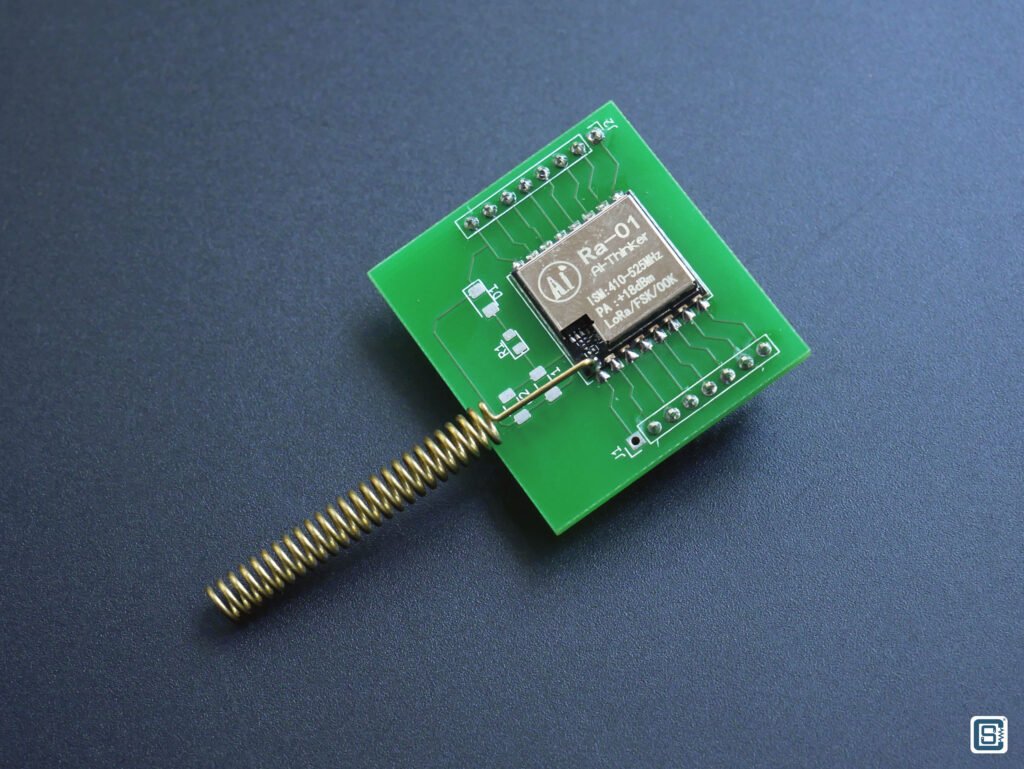
The RA-01 (spiral antenna) and RA-02 (SMA connector) modules from Ai-Thinker use SX1278 and the ones we have in hand work in the 433 MHz band. Even though that band is not allowed to be used in India, we will limit the use to experiments only. For any applications, you should get modules based on SX1276/SX1277/SX1279. There is an RFM95W-compatible SX1276-based LoRa module at RoboKits. The SX127x series chips use SPI (Serial Peripheral Interface) for communicating with a microcontroller.
Features & Specs
- LoRa Modem 168dB maximum link budget
- +20dBm – 100mW constant RF output vs. V supply
- +14dBm high-efficiency PA
- Programmable bit rate up to 300kbps
- High sensitivity: down to -148dBm
- Bullet-proof front end: IIP3 = -11dBm
- Excellent blocking immunity
- Low RX current of 9.9mA, 200nA register retention
- Fully integrated synthesizer with a resolution of 61Hz
- FSK, GFSK, MSK, GMSK, LoRa, and OOK modulation
- Built-in bit synchronizer for clock recovery
- Preamble detection
- 127dB Dynamic Range RSSI
- Automatic RF Sense and CAD with ultra-fast AFC
- Packet engine up to 256 bytes with CRC
- Built-in temperature sensor and low battery indicator
- SPI interface for microcontroller communication
- QFN-28 package
- 1.8 to 3.7V operating voltage
Pinout

| Number | Name | Type | Description |
|---|---|---|---|
| 0 | GROUND | – | Exposed ground pad |
| 1 | RFI_LF | I | RF input for bands 2&3 |
| 2 | VR_ANA | – | Regulated supply voltage for analog circuitry |
| 3 | VBAT_ANA | – | Supply voltage for analog circuitry |
| 4 | VR_DIG | – | Regulated supply voltage for digital blocks |
| 5 | XTA | I/O | XTAL connection or TCXO input |
| 6 | XTB | I/O | XTAL connection |
| 7 | NRESET | I/O | Reset trigger input |
| 8 | DIO0 | I/O | Digital I/O, software configured |
| 9 | DIO1/DCLK | I/O | Digital I/O, software configured |
| 10 | DIO2/DATA | I/O | Digital I/O, software configured |
| 11 | DIO3 | I/O | Digital I/O, software configured |
| 12 | DIO4 | I/O | Digital I/O, software configured |
| 13 | DIO5 | I/O | Digital I/O, software configured |
| 14 | VBAT_DIG | – | Supply voltage for digital blocks |
| 15 | GND | – | Ground |
| 16 | SCK | I | SPI Clock input |
| 17 | MISO | O | SPI Data output |
| 18 | MOSI | I | SPI Data input |
| 19 | NSS | I | SPI Chip-select input |
| 20 | RXTX/RF_MOD | O | Rx/Tx switch control: high in Tx |
| 21 | RFI_HF (GND) | I (-) | RF input for band 1 (Ground) |
| 22 | RFO_HF (GND) | O (-) | RF output for band 1 (Ground) |
| 23 | GND | – | Ground |
| 24 | VBAT_RF | – | Supply voltage for RF blocks |
| 25 | VR_PA | – | Regulated supply for the PA |
| 26 | GND | – | Ground |
| 27 | PA_BOOST | O | Optional high-power PA output, all frequency bands |
| 28 | RFO_LF | O | RF output for bands 2&3 |
Ai-Thinker RA-01/RA-02

RA-01 and RA-02 are SX1278-based LoRa modules produced by the company Ai-Thinker. The only difference between the two modules is that RA-01 has a solderable spiral antenna and RA-02 has a U.FL or IPEX connector for connecting an external antenna. So it’s just a matter of the convenience of connecting the antennas. Having an IPEX connector allows for connecting better gain antennas and positioning them flexibly.
Even though the SX127x series LoRa PHY chips can support a wide range of frequencies, some external parts like antenna matching, tuning, etc will be limited to only a select bandwidth. For those reasons, the same series of LoRa modules will come with different operating frequencies. The modules we are demonstrating here work in the 410-525 MHz range. Both modules are shielded to minimize EMI and have a maximum power output of +18 dBm (63.10 mW). In addition to the LoRa modulation, SX1278-based modules also support regular FSK (Frequency Shift Keying) and OOK (On-Off Keying) which are simpler to use but not robust as LoRa.
Specifications
| Property | Value |
|---|---|
| LoRa Chip | Semtech SX1278 |
| Package | SMD-16 module |
| Dimensions | 17 x 16 x 3.2 (±0.2) mm |
| Frequency Range | 410~525MHz |
| Communication Interface | SPI |
| SPI Frequency | 10 MHz |
| Programmable Bitrate | Up to 300 kbps |
| Maximum Transmit Power | 20±1 dBm |
| Receiver Sensitivity | -140 dBm |
| Working Voltage | 2.7~3.6V, 3.3V typical |
| Working Current | 140 mA |
| Minimum Receiving Current | 4.5 mA |
| Standby Current | 1.6 mA |
| Working Temperature | -20~+70°C |
| Storage Environment | -40 ~ +125°C, <90%RH |
| Weight | 0.45g |
Pinout


| Pin Number | Pin Name | Description | |
|---|---|---|---|
| RA-01 | RA-02 | ||
| 1 | – | ANT | Antenna |
| 2 | 1, 2 | GND | Ground |
| 3 | 3 | 3.3V | 3.3V power supply |
| 4 | 4 | RESET | Reset |
| 5 | 5 | DIO0 | Digital IO0, software configuration |
| 6 | 6 | DIO1 | Digital IO1 software configuration |
| 7 | 7 | DIO2 | Digital IO2 software configuration |
| 8 | 8 | DIO3 | Digital IO3 software configuration |
| 9 | 9 | GND | Ground |
| 10 | 10 | DIO4 | Digital IO 4-piece configuration |
| 11 | 11 | DIO5 | Digital IO5 software configuration |
| 12 | 12 | SCK | SPI clock input |
| 13 | 13 | MISO | SPI data output |
| 14 | 14 | MOSI | SPI data input |
| 15 | 15 | NSS | SPI chip select input |
| 16 | 16 | GND | Ground |
Schematic

Wiring
Since RA-01 is a module meant to be soldered directly onto a PCB, there is no provision for soldering pins. That said, we could still solder header pins on it if we really want, but we are going to use a small breakout board here to access the pins of the LoRa module with ease. We will also solder the supplied antennas directly on the module where there is a hole for it.
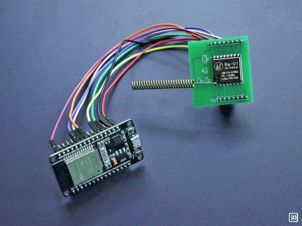
We are using the DOIT ESP32 DevKit V1 boards here. If you are not sure where the pins are or what their functions are, we have a complete pinout diagram and pin reference for ESP32. Connecting to the ESP32 is shown in the next table.
DOIT ESP32 DevKit V1 Wi-Fi Development Board – Pinout Diagram & Arduino Reference
We also have a getting-started tutorial on the ESP32 chip using the DOIT ESP32 DevKit V1 board.
Getting Started with Espressif ESP32 Wi-Fi & Bluetooth SoC using DOIT-ESP32-DevKit-V1 Development Board
| RA-01 Pin# | RA-01 Pin Name | ESP32 DevKit Pin | Arduino Instance |
|---|---|---|---|
| 1 | ANT | – | – |
| 2 | GND | GND | – |
| 3 | 3.3V | 3V3 | – |
| 4 | RESET | D2 (GPIO 2) | PIN_LORA_RST |
| 5 | DIO0 | D4 (GPIO 4) | PIN_LORA_DIO0 |
| 6 | DIO1 | – | – |
| 7 | DIO2 | – | – |
| 8 | DIO3 | – | – |
| 9 | GND | GND (No need to connect if GND is connected already) | – |
| 10 | DIO4 | – | – |
| 11 | DIO5 | – | – |
| 12 | SCK | D18 (GPIO 18) | PIN_LORA_SCK |
| 13 | MISO | D19 (GPIO 19) | PIN_LORA_CIPO |
| 14 | MOSI | D23 (GPIO 23) | PIN_LORA_COPI |
| 15 | NSS | D5 (GPIO 5) | PIN_LORA_CS |
| 16 | GND | GND (No need to connect if GND is connected already) | – |
There are multiple GND pins on the module. For testing, you only need to connect one of those GND pins to the ESP32 board. But if you are designing a PCB for the RA-01 module, you must tie all GND pins to a common GND. The power supply used for the LoRa module should be able to supply at least 200 mA current at 3.3V. It is also a good idea to place a Tantalum capacitor near to the VCC pin. But we are not using one in this experiment.
Code
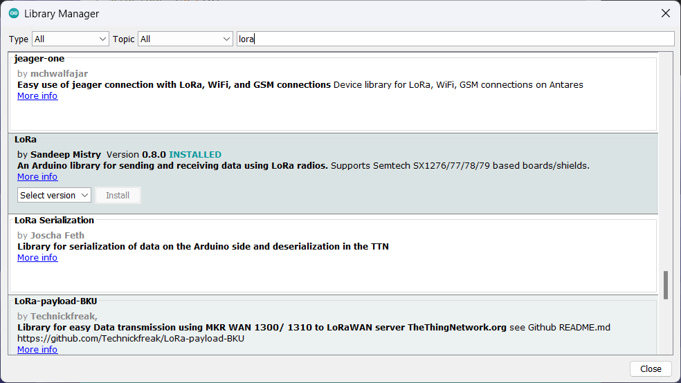
As we have seen, the RA-01 module uses an SPI interface to communicate with a host processor. So we need to use one of the SPI interfaces of ESP32 in the Arduino environment. But configuring the LoRa module and sending and receiving data is not simple or straightforward. One has to learn the entire datasheet of SX1278 and study its data registers in order to get it working the way we want. But writing such a driver library can be a daunting task. Fortunately, there are people who understood LoRa better and spent the time to write open-source Arduino libraries for everyone. Sandeep Mistry (@sandeepmistry) has published an open-source Arduino library for LoRa modules based on Semtech SX1276/77/78/79 series. We can use it to communicate with the RA-01 module.
You can install this library directly from the Arduino IDE by searching for “Lora” and looking for the one with Sandeep Mistry as the author. After installing the library, you can open the example sketches from File → Examples → Lora.
LoRa Sender
We have modified the LoRaSender sketch a little to improve the compatibility with the ESP32 board. Following is our LoRa Sender sketch.
//======================================================================//

#include <SPI.h>
#include <LoRa.h>

//======================================================================//

#define PIN_LORA_COPI   23
#define PIN_LORA_CIPO   19
#define PIN_LORA_SCK    18
#define PIN_LORA_CS     5
#define PIN_LORA_RST    2
#define PIN_LORA_DIO0   4

#define LORA_FREQUENCY  433E6

//======================================================================//

int counter = 0;

//======================================================================//

void setup() {
  Serial.begin (115200);
  while (!Serial);
  delay (1500);
  Serial.println ("LoRa Sender");

  LoRa.setPins (PIN_LORA_CS, PIN_LORA_RST, PIN_LORA_DIO0);
  LoRa.setSPIFrequency (20000000);
  LoRa.setTxPower (20);

  if (!LoRa.begin (LORA_FREQUENCY)) {
    Serial.println ("Starting LoRa failed!");
    while (1);
  }
  else {
    Serial.print ("LoRa initialized with frequency ");
    Serial.println (LORA_FREQUENCY);
  }
}

//======================================================================//

void loop() {
  Serial.print ("Sending packet: ");
  Serial.println (counter);

  // send packet
  LoRa.beginPacket();
  LoRa.print ("Hello LoRa ");
  LoRa.print (counter);
  LoRa.endPacket();

  counter++;

  delay (1000);
}

//======================================================================//
We begin the sketch by adding the header files for SPI and LoRa. If you have multiple LoRa libraries installed from multiple authors, there is a chance that the Arduino IDE will complain about conflicting libraries. This can happen if different libraries use the same names for their source files. Unfortunately, there is no way of telling the Arduino IDE which library we want to use. So you need to temporarily move the conflicting libraries from your libraries folder.
We are defining the pins as macro constants so that we can easily change them if required. Also, it is a good practice to have all pins in the same place. We are also setting the LoRa frequency to 433 MHz by defining the value 433E6 (E is just the exponent notation). The counter is a variable we will increment after each transmission.
In the setup() function, we are initializing the Serial port for printing debug messages. Then we will use the setPins() function from the LoRa library to set the additional control pins for the RA-01 LoRa module. We can use any GPIO pins for these functions, but we must tell the library about it. The library takes care of initializing these pins to proper modes. By default, the library will use the default SPI interface defined by the Arduino environment which is SPI (SPI0) for ESP32. The pins for this interface are already defined and are known to the LoRa library. So we don’t need to specify them additionally.
After that, we can use the setSPIFrequency() to set the SPI frequency in Hz. There will be a default SPI frequency defined somewhere but you can also change it whenever you want. setTxPower() is used to set the output power in dBm. We must use the function in conjunction with the LoRa object. This object is already instantiated by the library. In order to initialize the module, we must call the begin() function with the frequency we want. In case some parameters are not correct or something else is not right, the initialization will fail. It can fail if the wiring is wrong, or broken, or if the SPI speed and mode are wrong. The code won’t proceed if the initialization fails.
If the initialization is successful, we will enter the loop() function and begin sending data through the RA-01 LoRa module. You need to have another ESP32 board interfaced with an RA-01 module and connected to the computer in order to receive the data we are sending. Sending data is very easy using the library. We can begin a packet by calling the beginPacket() function and subsequently calling print() functions to add our data to a temporary buffer. Data will be only sent when we call endPacket(). Kudos to Sandeep for making the API as intuitive as possible. The print() function is inherited from the standard output function and therefore you get all the formatting options with it. Very handy.
We will send a “Hello LoRa <couner value>” message and increment the counter. We will wait for some time before sending a new message. Obviously, most of the LoRa configurations and complexities are hidden from us, and that’s how abstraction works. The library uses default values for all parameters that are not set by the user. Still, Sandeep gives us a few additional functions to set the SF, coding rate, bandwidth, preamble, sync word, and more. You can find the complete API documentation in his GitHub repository. Below is the output from the serial monitor.

LoRa Receiver
We have also modified the LoRaReceiver sketch. The initializing part is the same as the Sender sketch. In the loop() function, however, we listen for new LoRa packets and print any new message we get along with the RSSI (Received Signal Strength Indication). RSSI is a parameter that tells how good the signal strength was for the last received message. We can use it to roughly estimate the distance to the transmitter if we know the power at which the transmitter is transmitting. A good signal strength is what we always need.
//======================================================================//

#include <SPI.h>
#include <LoRa.h>

//======================================================================//

#define PIN_LORA_COPI   23
#define PIN_LORA_CIPO   19
#define PIN_LORA_SCK    18
#define PIN_LORA_CS     5
#define PIN_LORA_RST    2
#define PIN_LORA_DIO0   4

#define LORA_FREQUENCY  433E6

//======================================================================//

void setup() {
  Serial.begin (115200);
  while (!Serial);
  delay (1500);
  Serial.println ("LoRa Receiver");

  LoRa.setPins (PIN_LORA_CS, PIN_LORA_RST, PIN_LORA_DIO0);
  LoRa.setSPIFrequency (20000000);

  if (!LoRa.begin (LORA_FREQUENCY)) {
    Serial.println ("Starting LoRa failed!");
    while (1);
  }
  else {
    Serial.print ("LoRa initialized with frequency ");
    Serial.println (LORA_FREQUENCY);
  }
}

//======================================================================//

void loop() {
  // try to parse packet
  int packetSize = LoRa.parsePacket();

  if (packetSize) {
    // received a packet
    Serial.print ("Received packet '");

    // read packet
    while (LoRa.available()) {
      Serial.print ((char) LoRa.read());
    }

    // print RSSI of packet
    Serial.print ("' with RSSI ");
    Serial.println (LoRa.packetRssi());
  }
}

//======================================================================//
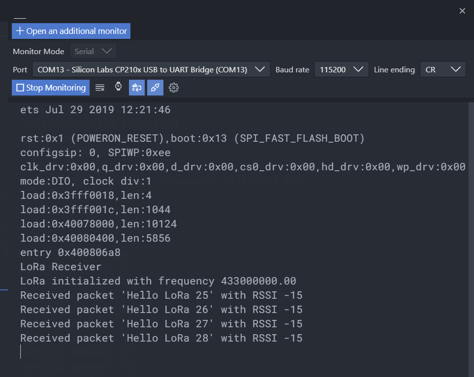
Reading an incoming packet is accomplished by calling the parsePacket() function. This function will read the incoming message to a buffer ready for us to read, and return the number of bytes available. If the available number of bytes is greater than 0, that means we have received a new message. We can read the message with the read() function which will return a single byte at a time. If our RA-01 LoRa transmitter is working and our receiver is in the range, we will continuously get new messages every second as shown in the serial monitor screenshot below.
We hope we were able to give you a good overview of the LoRa communication system starting from the CSS modulation and the important parameters involved. It will help you better understand how LoRa works and how to choose the working configuration correctly. But this is just the tip of the iceberg. RF communication is a complex topic involving complicated math and concepts. Understanding them in detail is crucial for building an actual product based on LoRa. We will publish more tutorials on LoRa using various other modules in the future. If you have any suggestions to improve our post, please let us know in the comments.
Links
- RA01/RA-02 Datasheet [PDF]
- RA-01/RA02 Documentation from Ai-Thinker
- LoRa Spreading Factor Explained – Tomas Tulka
- Electromagnetic Waves – TechnologyUK
- LoRa Modem – Designer’s Guide [PDF]
- What are LoRa® and LoRaWAN®? – LoRa Developer Portal
- Understanding the relationship between LoRa chips, chirps, symbols and bits
- LoRa PHY Frame Format Explained
- Complete Reverse Engineering of LoRa PHY – Tapparel Joachim [PDF]
- LoRa Video Tutorials – Mobilefish.com
- LoRa PHY based on GNU Radio
Short Link
- Short URL to this page – https://circuitstate.com/ra01esp32


Can you send me the schematic of the card you made, I’d like to see what and where you added extras?
We do not have the schematic right now. But the added extra items are simply two capacitors on the VDD and a power indication LED along with its resistor.
I’m going to try to do my first project with LoRa, a water level transmitter for a water tank (based on an ultrasonic sensor) and a receiver that will control a pump, but I’ll do it with Atmega328P. Your information helped me a lot. Thank you very much. Daniel – Brazil.
Glad to hear that and good luck with your project 😀
I’m going to work on an exactly similar project here in Spain. Right now my main difficulty is with erroneous payloads received around in 2% of the messages sent.
How to make a sms device with esp32 and lora module with handshaking while sending and receiving messages
If you want to create a text messaging device with LoRa as the wireless interface, then you need some way of addressing the devices so that you can send messages to just one device at a time. For that, you can use basic Asymmetrical key sharing as the handshaking mechanism. Every node has to have a Public Key and Private Key. Public Keys of all devices will be known to all devices on your network. When device A wants to send a message to B, A uses B’s Public Key to send two pieces of information – 1. A’s Public Key, 2. A unique random number. When B receives the message, only B can decipher it with its own Private Key. And so B is able to read A’s Public Key and the unique random number sent by A. B then creates a response message with 1. The random number sent by A, 2. A new random number generated by B, and encrypts it with A’s public key. Only A will be able to decipher this message sent by B. Once A decipher the message from B, it gets both its own random number and the one generated from B, which verifies that communication. After that, the nodes can share more keys if needed and have secure communication from there on.