Interfacing R307 Optical Fingerprint Scanner with Arduino Boards for Biometric Authentication
Tutorial on interfacing R307 optical fingerprint scanner with Arduino development boards along with Arduino library. Fingerprint scanners can be used for biometric authentication.
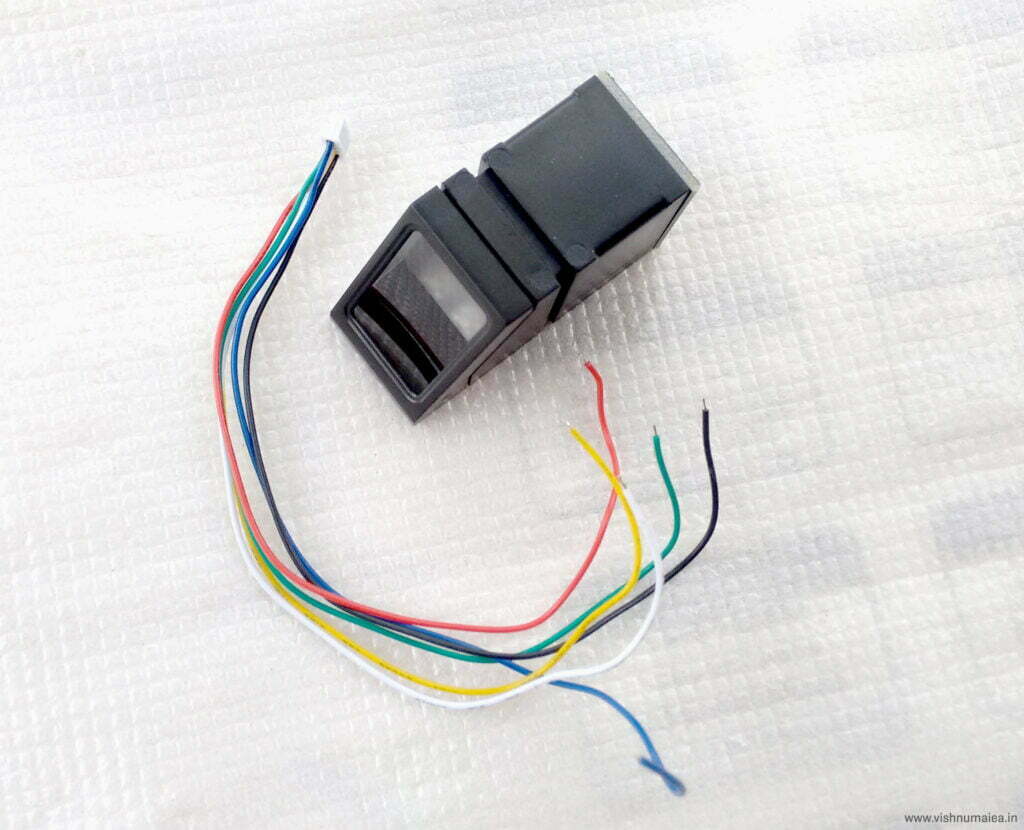
Fingerprints are one of the many unique biometric signatures we can use to identify people very accurately. But just by holding someone’s hand and staring at their fingers can’t be practical 😁; we’re not good at it. But computers are good at recognizing and matching patterns very fast and accurately. Before we can process a fingerprint pattern with a computer, we must “capture” it.
There exist many methods to digitize fingerprints; from forensic methods to ultrasound scanning. In this tutorial, we will learn how an Optical Fingerprint Scanner works and how we can interface the R307 fingerprint scanner module to an Arduino board. R307 is an optical fingerprint scanner module from the R30X series produced by a Chinese vendor called Hangzhou Grow Technology Co., Ltd. Other sensors in the series include R300, R301T, R302, R303, R303T, R305, R306, R308, and R311, some of which are capacitive sensors. Despite using different sensing techniques and form-factors, they all share the same interface and command set. Therefore, it is easy to adapt the library that you find here for other models as well.
Specifications
- Power Supply : DC 4.2V-6V
- Current Consumption : ~50mA
- Interface : UART and USB
- Baudrate : (9600 * N) bps, N = 1-12, default is 6
- Image Acquiring Time : <0.5s
- Matching Modes : 1:1, 1:N
- Character File Size : 256 Bytes
- Template Size : 512 Bytes
- Storage Capacity : 1000
- Security Levels : 5
- FAR (False Acceptance Rate) : <0.001%
- FRR (False Recognition Rate) : <0.1%
- Average Searching Time : <1s (1:1000)
- Window Dimensions : 19 * 21 mm
- Working Environment : Temp = -10°C – +40°C, RH = 20%-80%
- Storage Environment : Temp = -40°C – +85°C, RH = <85%
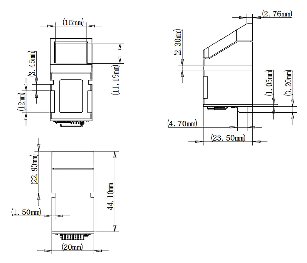
- Outline Dimensions : Split Type, 44.1 * 20 * 23.5 mm
How Does An Optical Fingerprint Scanner Work?
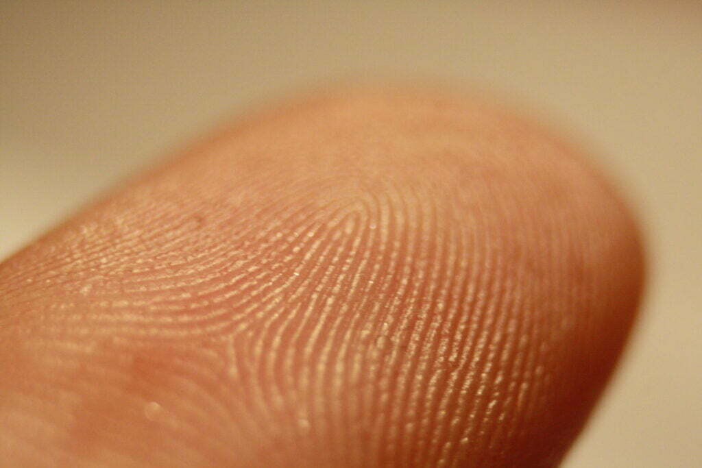
The skin on the palms of our hands has a special pattern called friction ridges that help us grab things effectively without slipping. These patterns consist of ridges and valleys arranged in certain configurations and are unique for each individual. Our fingertips also have them as you can see from the above image. When a finger comes in contact with a surface, the ridges make strong contact with it. When we strongly grab something, the moisture, oil, dirt, and dead skin cells on our finger can attach to the surface of the thing we are grabbing, leaving an impression we call a fingerprint. Various forensic methods involving the use of chemicals are used to extract such fingerprints from crime scenes and are called latent fingerprints. But an optical fingerprint scanner works a bit differently.
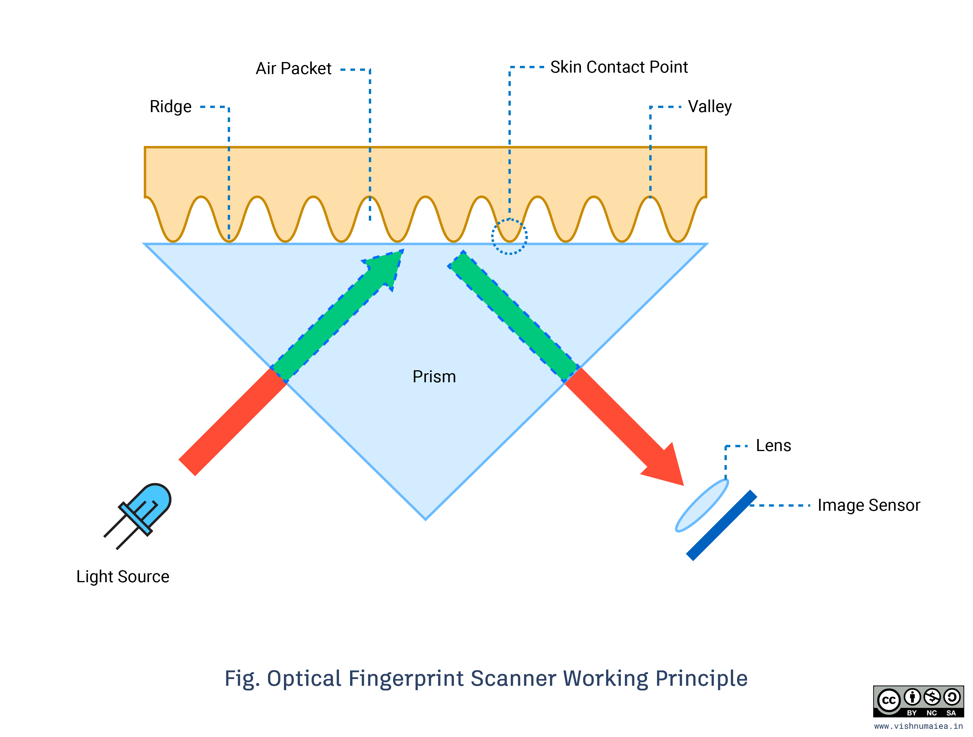
An optical fingerprint scanner works based on the principle of Total Internal Reflection (TIR). In such a scanner, a glass prism is used to facilitate TIR. Light from an LED (usually blue color) is allowed to enter through one face of the prism at a certain angle for the TIR to occur. The reflected light exits the prism through the other face where a lens and an image sensor (essentially a camera) are placed.
When there is no finger on the prism, the light will be completely reflected off from the surface, producing a plain image in the image sensor. When TIR occurs, a small amount of light is leaked to the external medium and it is called the Evanescent Wave. Materials with different refractive indexes (RI) interact with the evanescent wave differently. When we touch a glass surface, only the ridges make good contact with it. The valleys remain separated from the surface by air packets. Our skin and air have different RIs and thus affect the evanescent field differently. This effect is called Frustrated Total Internal Reflection (FTIR). This effect alters the intensities of the internally reflected light and is detected by the image sensor (see this image). The image sensor data is processed to produce a high-contrast image which will be the digital version of the fingerprint.
In capacitive sensors, which are more accurate and less bulky, there is no light involved. Instead, an array of capacitive sensors are arranged on the surface of the sensor and allowed to come in contact with the finger. The ridges and air packets affect the capacitive sensors differently. The data from the sensor array can be used to generate a digital image of the fingerprint.
Construction & Disassembly
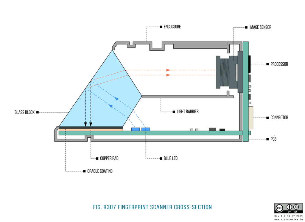
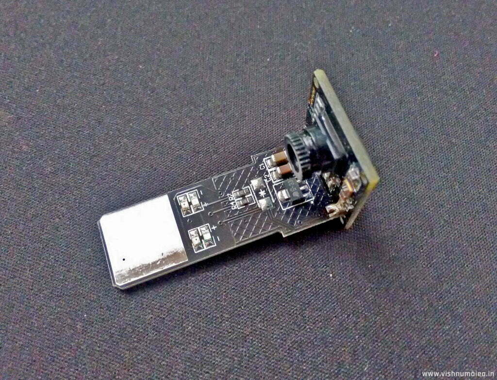
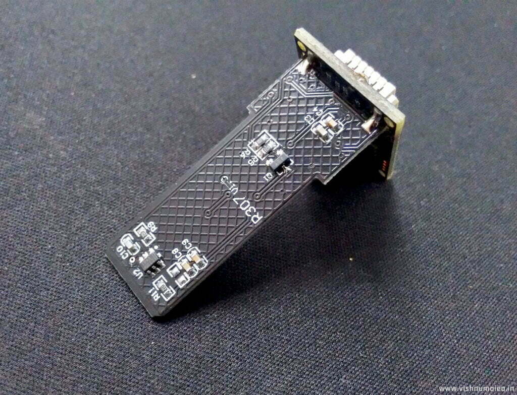
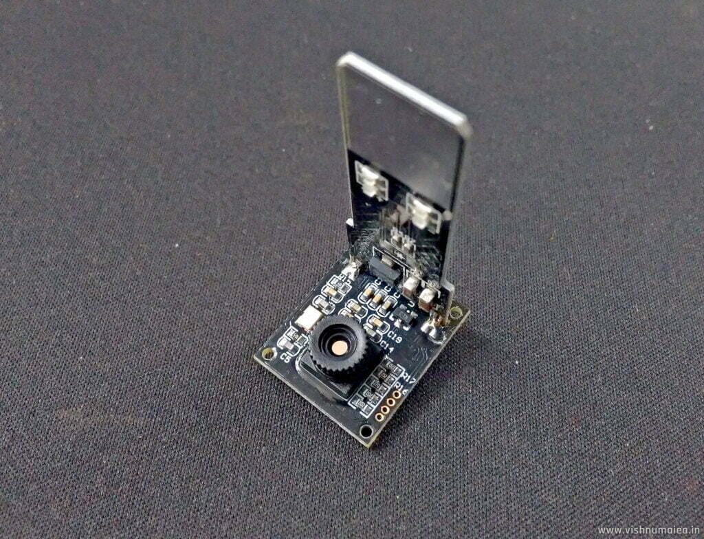
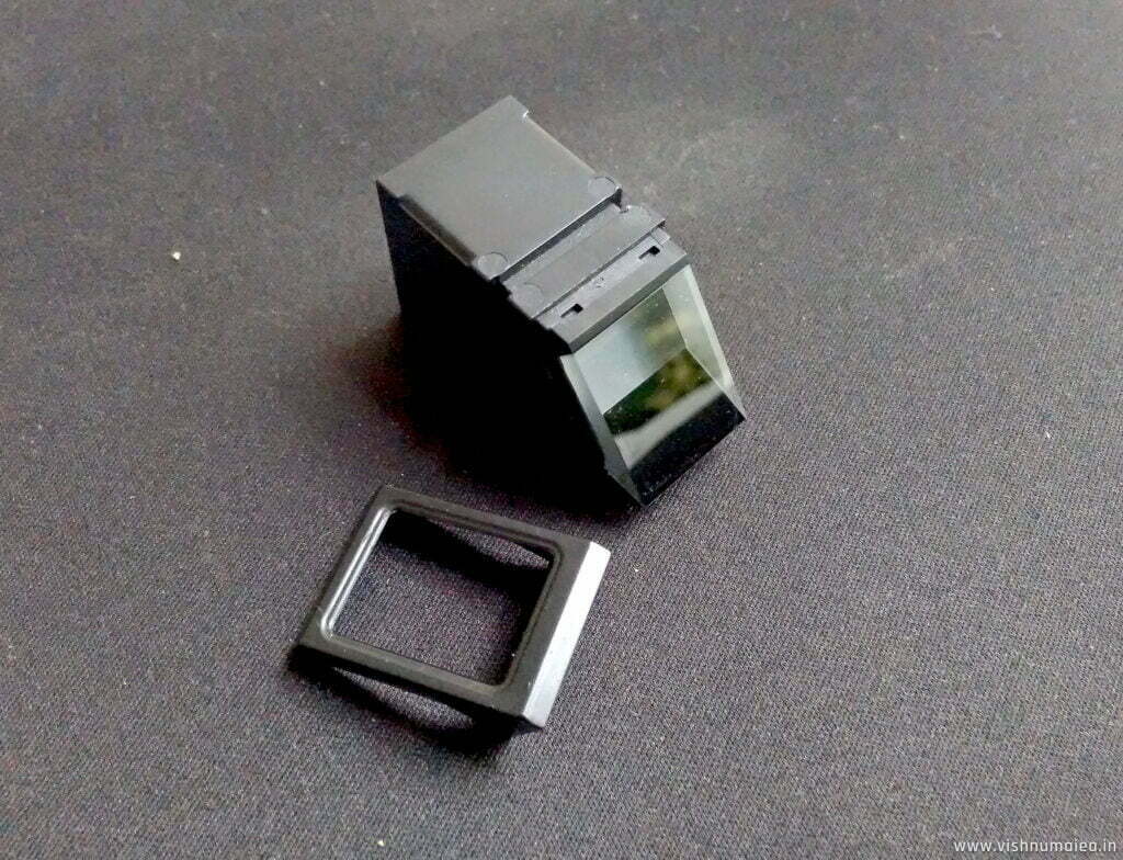
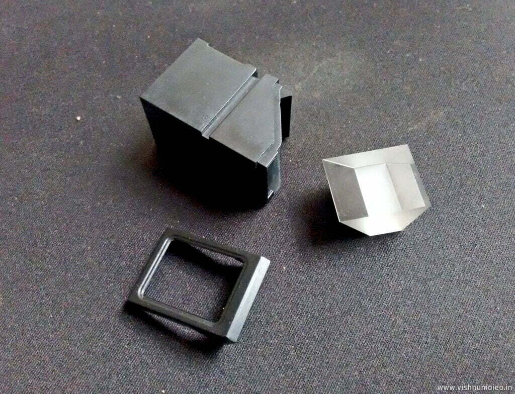
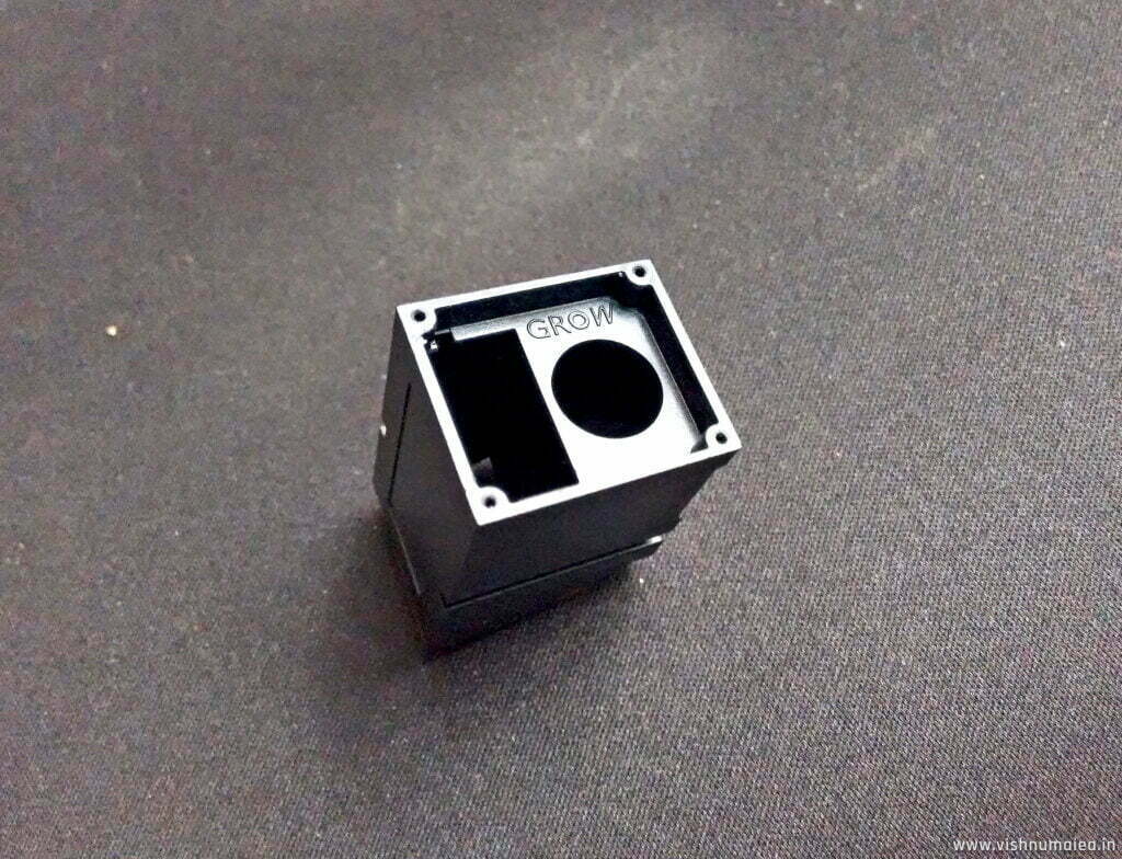
Above is a cross-sectional diagram I made to better understand the construction (illustrative only, not a physically exact one). Opening the module was easy; there are four Philips screws on the back. Unscrew them and you can remove the PCB. There are two PCBs; one arranged horizontally and one vertically (shown in washed green). These PCBs are connected by solder. The four blue LEDs and the touch sense pad are on the horizontal PCB. The vertical PCB has the image sensor, the processor, and the connector. When inserted, the touch sense pad comes in contact with the glass block above. The image sensor is soldered and glued. Strangely, I couldn’t find any lens on it. Maybe it doesn’t need one. The enclosure has an internal barrier to separate the light from the LEDs and the light coming out of the prism. On the bottom side of the prism, a black epoxy is coated which gives a high-contrast background for the fingerprint image. To access the prism, remove the cap on the front.
Mechanical Diagram
Pinout
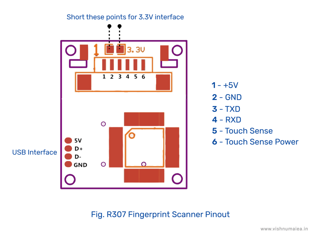
| Pin Number | Name | Type | Description |
| 1 | +5V | IN | Positive Supply (DC 4.2V-6V) |
| 2 | GND | GND | Supply Ground |
| 3 | TXD | OUT | Data output (TTL) |
| 4 | RXD | IN | Data input (TTL) |
| 5 | Touch | OUT | Finger detection signal (max output current: 50mA) |
| 6 | 3.3V | IN | Finger detection power (DC 3.3V-5V ~5uA) |
The scanner can be interfaced and powered from both 3.3V and 5V supplies. The working voltage of the scanner controller is always 3.3V. There is a 3.3V regulator on the PCB. The 5V supply you provide goes to the input of that regulator, and the 3.3V you supply bypasses the regulator and goes directly to the fingerprint scanner controller.
When you want to power the scanner from 5V and interface with a 5V microcontroller, supply the power to pins 1 and 6, and disconnect the 3.3V jumper shown in the picture. If you want to supply 3.3V and interface the scanner with a 3.3V microcontroller such as Arduino Due, supply the power to pins 1 and 6 and short the 3.3V jumper. Improper voltages and configurations might damage the controller. So be careful with it.
Pin 6 (Touch Sense Power) is the supply voltage for the finger detection circuit. When a finger is present on the scanner, the output of pin 5 (Touch Sense) becomes HIGH. This signal can be used to initiate the scanning of the finger manually. Otherwise, the scanner will wait for some time to detect the finger.
The R307 has both USB and UART interfaces. With the USB, you can directly connect the scanner to a computer and communicate with it. A virtual COM port will be created when you connect the scanner to a Windows PC. If you want to interface the scanner with a microcontroller, you can use the UART interface which supports baud rates up to 115200 bps.
Module Schematic
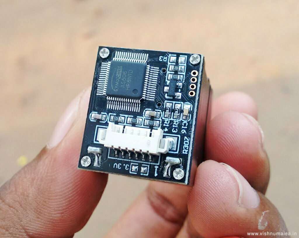
The main controller on the PCB is AS606 from a company called Synochip. AS606 is a microcontroller with Cordis 5+ RISC cores and has everything needed for a performance controller including a DSP. If you want to know more about the controller check out the datasheet.
The R307 Manual is the only document to our rescue, and it is ambiguous in many places. The R30X Series Manual has some more information. The below schematic is included in the manual.
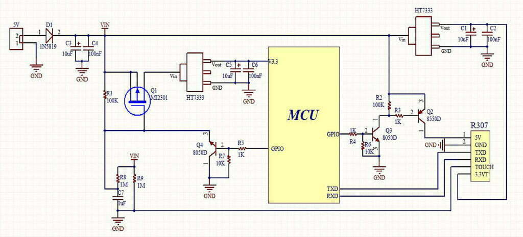
The schematic is incomplete and full of errors. For example, in the schematic, you can see that the TOUCH output pin is directly connected to the ground. And there are many such inconsistencies. If you look at the manuals of other modules in the series, the same schematic can be seen included in them.
When I disassembled the module, I could see there was an IC TTP233D from Tontek, which is a touch sense detector. The TOUCH pin is actually connected to the output pin (pin 1) of the IC, which I verified using a multimeter. The resistor R9 is possibly a pull-up. The input pin of the IC is connected to the copper pad on the horizontal PCB. There is some kind of black glue on the side of the glass block between the copper pad. I don’t know if that opaque coating has any other functions other than providing a high-contrast background for the fingerprint image. But I assume, when we touch the glass, the change in capacitance is detected by the touch-sensing IC via the copper pad, and a digital output is driven at the TOUCH pin. This is in contrast to the schematic the company provided. Somebody skipped their job!
Memory and Registers
The fingerprint scanner has multiple registers and memory buffers to store configurations and fingerprint data. These are explained below.
- Notepad – This is 512 bytes of non-volatile (content is not lost when power is turned off) flash memory. It is logically divided into 16 pages with 32 bytes each. Instructions
GR_WriteNotepadandGR_ReadNotepadcan be used to access this memory. When writing a page, it is taken as a whole and the contents are replaced. - Image Buffer – Image buffer is used to store a BMP image of size 256 x 288, each pixel occupying a byte. This buffer is part of the RAM and the contents are lost when power is turned off.
- Character File Buffer – A character file is a processed high-contrast image of a fingerprint. Two character files from two consecutive scans are combined to form a template file which is the final version of the fingerprint that is stored in the fingerprint library (not to be confused with the Arduino library. The Fingerprint library is the memory used to store up to 1000 fingerprints). The two character file buffers are
CharBuffer1andCharBuffer2each with a size of 512 bytes. - Fingerprint Library – This is a section of the flash memory where 1000 fingerprint templates can be stored. Templates are arranged sequentially with numbering from 0 to N-1 (The manual says 0-N) where N is the capacity of the library determined by the size of the flash memory. There are instructions to store, process and delete templates from this memory. They will be explained later.
- System Configuration Register – This is a 16-byte long register bank containing operating parameters and statuses. Except for the device address which takes up 4 bytes, the rest of the parameters are 2 bytes (a word) in length. The command ReadSysPara can be used to read, and the command
SetSysParacan be used to write this register bank.
| Name | Description | Offset (word) | Size (word) |
| Status Register | Contents of system status register | 0 | 1 |
| System Identifier Code | Fixed value: 0x0009 | 1 | 1 |
| Library Size | Fingerprint library size | 2 | 1 |
| Security Level | Security level (1, 2, 3, 4, 5) | 3 | 1 |
| Device Address | 32-bit device address | 4 | 2 |
| Data Packet Size | Size code (0, 1, 2, 3) | 6 | 1 |
| Baud Multiplier | N (baud = 9600*N bps) | 7 | 1 |
The Status Register indicates the current operation status of the module and comprises the following,
| Bit Number | 15-4 | 3 | 2 | 1 | 0 |
| Description | Reserved | ImgBufStat | PWD | Pass | Busy |
where
- Busy =
1: system is executing commands0: system is free
- Pass =
1: found a matching fingerprint0: fingerprint not found
- PWD =
1: handshaking password verified0: password not verified
- ImgBufStatus =
1: image buffer contains valid image0: image buffer does not have a valid image.
System Identifier Code is a fixed value that determines the type of module. Its value is 0x0009 for R307.
Library Size is the number of templates that can be stored in the module. The maximum value for this parameter is 1000 for R307.
Security Value determines the threshold for fingerprint searching and matching. Its value can be from 1 to 5. When it is 1, the FAR (False Acceptance Rate) is the highest, and FRR (False Recognition Rate) is the lowest. FAR is simply the number that determines how likely the module will identify a weakly matched fingerprint as positive. FRR is how likely the module will identify a wrong fingerprint as negative. At level 5, the FAR is the lowest and FFR is the highest. In this setting, it can be difficult to match your fingerprint.
Device Address is a 32-bit value that holds the address of the module. The correct address is needed to communicate with the module. If you don’t send the correct address, the module won’t execute any commands. The device address can be modified with the command SetAddr. The factory-programmed address is 0xFFFFFFFF. There are no methods specified in the manual to reset the address to default, so keep the address recorded somewhere if you ever change it.
Data Packet Size determines the maximum length of data contained in a single packet. Its value can be 0-3 where 0 = 32 bytes, 1 = 64 bytes, 2 = 128 bytes and 3 = 256 bytes.
Baud Multiplier sets the UART communication speed of the module. The minimum speed is 9600bps and can be set to up to 12 times of that which is 115200bps. The multiplier value N can be from 1-12 and the effective speed will be (9600*N) bps. The default baudrate is 57600bps.
R307 Communication Protocol
Both UART and USB interfaces use a common serial communication protocol based on a packet format (the manual refers to packets as “packages”). All data and commands are to be sent as data packets and all responses from the module will also be packets. Therefore, we need to frame data and commands as packets before sending out, and must extract data from response packets. The UART frame format is 10 bits long with 1 start bit, 1 stop bit, and 8 data bits.

The packet format is as follows (length in bytes is shown in brackets),
| Header (2) | Address (4) | Packet Identifier (1) | Packet Length (2) | Packet Content (Instruction/Data/Parameter) | Checksum (2) |
If you feel confused, the UART frame is how a byte of data is transferred via the UART interface. A packet is a group of many such bytes (or frames). Let’s see the definitions of each part.
- Header : This indicates the start of a packet. It has to be the fixed value
0xEF01. It is 2 bytes long and the high byte is always transferred first. - Address : This is the 32-bit address of the scanner module. The module will accept instructions only if the address we are sending matches the address stored in the module. The default address is
0xFFFFFFFFand can be modified withSetAddrinstruction. - Packet Identifier : This determines what type of packet we’re sending or receiving. It is 1 byte long and depending on the value the packet types can be,
0x01: The packet contains a command.0x02: Data packet. A data packet must be followed by a command packet or acknowledge packet.0x07: Acknowledge packet. It is sent by the module in response to a command.0x08: End of data transfer packet. When we send large-volume data such as an image, the data transfer will be terminated by this packet.
- Packet Length : This is the total length of Packet Content and Checksum in bytes. The maximum length is 256 bytes and the high byte is transferred first.
- Packet Content : This can be data/command/parameters etc. of varying length. The Packet Length is the value that specifies the length of the data in bytes.
- Checksum : This is the arithmetic sum of all bytes in Packet Identifier, Packet Length and Packet Content. Overflowing bits are ignored. MSB part is always transferred first.
In order to make the fingerprint scanner work, we must send instructions or commands in the form of packets. Each instruction is simply a 1-byte code that we must include in the packet. The module responds to each instruction with an acknowledgment packet that describes the result and status of command execution. Each instruction has a set of expected response codes found in the ACK packet that is called confirmation codes. Instructions and their byte codes are grouped according to their functions as shown below,
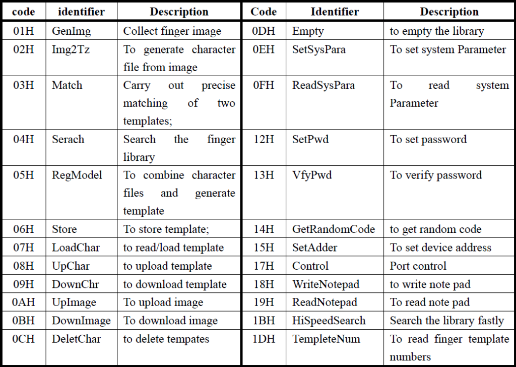
Following is the list of confirmation codes.
0x00– Command execution complete0x01– Error when receiving a data package0x02– No finger on the sensor0x03– Failed to enroll the finger0x04– Failed to generate character file due to the over-disorderly fingerprint image0x05– Failed to generate character file due to the over-wet fingerprint image0x06– Failed to generate character file due to the over-disorderly fingerprint image0x07– Failed to generate character file due to lack of character point or over-smallness of fingerprint image0x08– Finger doesn’t match0x09– Failed to find a matching finger0x0A– Failed to combine the character files0x0B– Addressing PageID is beyond the finger library0x0C– Error when reading template from library or the template is invalid0x0D– Error when uploading template0x0E– Module can’t receive the following data packages0x0F– Error when uploading image0x10– Failed to delete the template0x11– Failed to clear finger library0x13– Wrong password0x15– Failed to generate the image0x18– Error when writing flash0x19– No definition error0x21– Password not verified0x1A– Invalid register number0x1B– Incorrect configuration of register0x1C– Wrong notepad page number0x1D– Failed to operate the communication port0x41– No finger on the sensor when adding fingerprint on the second time0x42– Failed to enroll the finger for the second fingerprint scan0x43– Failed to generate character file due to lack of character point or over-smallness of fingerprint image for second fingerprint scan0x44– Failed to generate character file due to the over-disorderly fingerprint image for the second fingerprint scan0x45– Duplicate fingerprint- Others – System reserved
The confirmation code 0x21 is not listed in the manual but I found it when working with the module. It will be sent when we try to execute commands without verifying the password first.
All the commands and their response codes are explained in detail in the manual. So it would be redundant to do it here. But let’s look at the VfyPwd instruction and its corresponding packet as an example.
| 2 bytes | 4 bytes | 1 byte | 2 bytes | 1 byte | 4 bytes | 2 bytes |
| Header | Address | Packet Identifier | Packet Length | Instruction Code | Data (Password) | Checksum |
0xEF01 | 0xFFFFFFFF | 0x01 | 0x07 | 0x13 | 0x6F6F6F6F | 0x01D7 |
Above is the packet format for verifying password. Address is assumed to be the default one. We’re sending out a command, and so the Packet Identifier has to be 0x07. The Packet Length will be always 7 for this instruction. The Packet Content is split into Instruction Code and Password. Password is 0x6F6F6F6F for our example. If we calculate the Checksum of the bytes, it will be 0x01D7 which is two bytes long.
If the address and password are correct and the packet is correctly formatted, the module will respond with the following acknowledgment packet,
| 2 bytes | 4 bytes | 1 byte | 2 bytes | 1 byte | 2 bytes |
| Header | Address | Packet Identifier | Packet Length | Confirmation Code | Checksum |
0xEF01 | 0xFFFFFFFF | 0x01 | 0x03 | 0x00 | 0x04 |
The confirmation code will be 0x00 if our password was correct, and 0x13 if it was not.
Interfacing with PC Application
A Windows application is available to test products in the R30X series. You would find two versions of it if you search online. One is called SFG Demo and the other is SYNO Demo. The latter one was found to be better, so I will be demoing that here. You can download both versions in the downloads section.
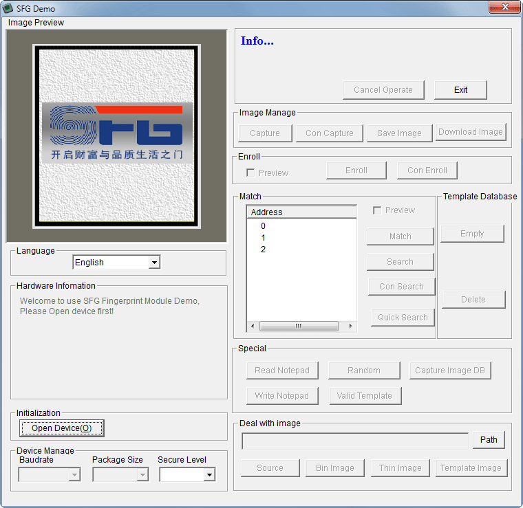
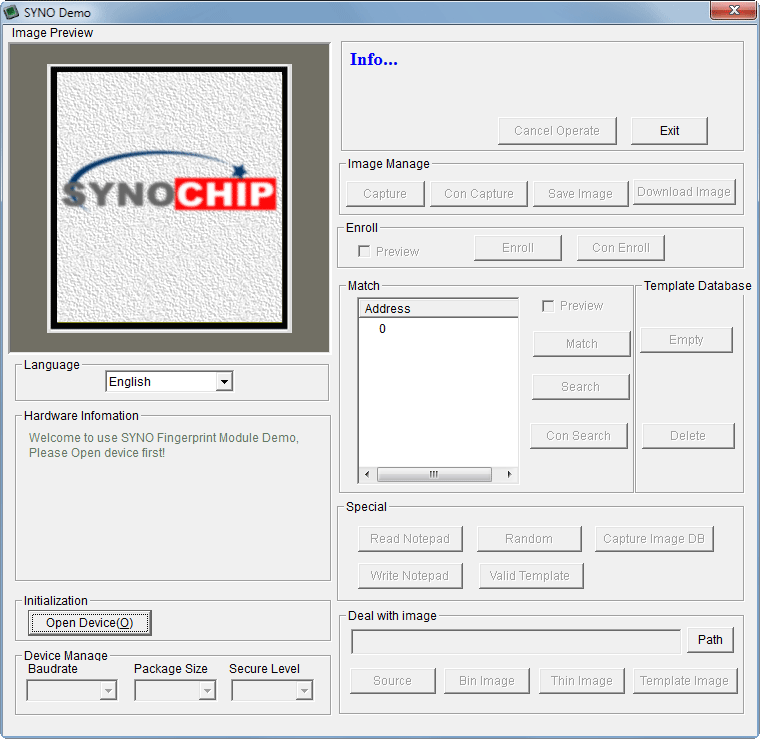
You can either connect the module directly to the computer via USB or through a USB-UART converter module. In both cases, a virtual COM port will be established in Windows. Then open the SYNO Demo software and use the Open Device button to choose the COM port. You could encounter an issue here. Instead of fetching the list of active COM ports from the OS, the application has a set of predefined COM port numbers. This is from 1-16 in the SYNO Demo software. So if the COM port assigned to your fingerprint module or the USB-UART module is greater than 16, you won’t be able to connect. In that case, go to Device Manager and change the COM port number for your module. If an active device was found, its details will be shown in the Hardware Information window with a success message.
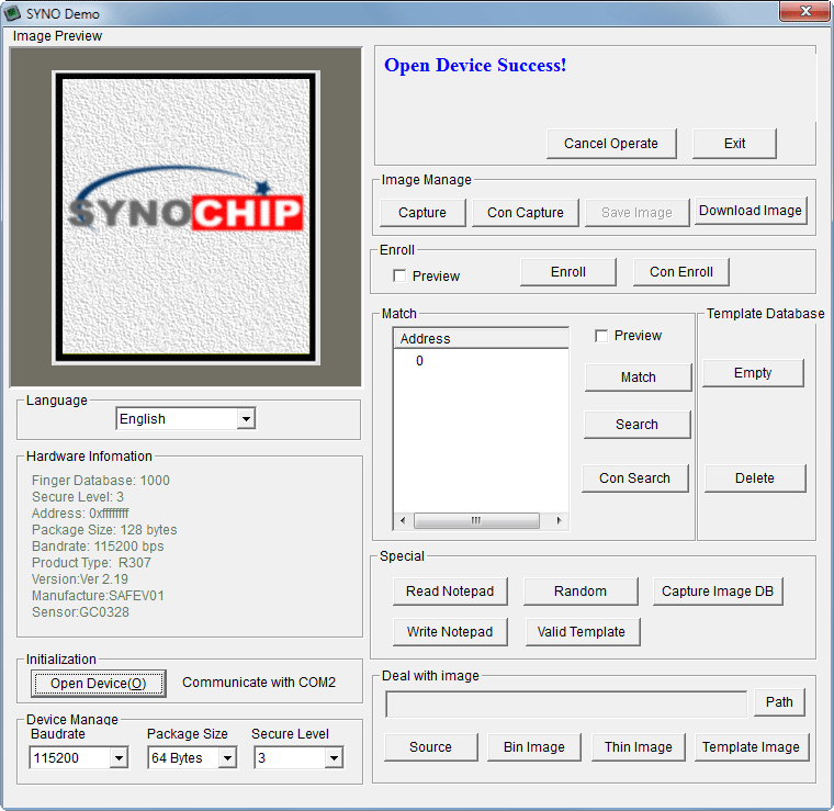
You will come across many inconsistencies and typos while using the software. But that is to be expected when the Chinese make English versions of their applications and manuals. Other features of the application are straightforward. A more detailed tutorial on the application can be found here, though for a different version of the module.
R30X Arduino Library
We have published an open-source library on GitHub for interfacing R307 and other R30x series fingerprint scanners with all Arduino-compatible development boards. The complete documentation is available on a separate post. Find the links to the documentation and GitHub repository below.
- R307 Optical Fingerprint Scanner – Arduino Library Documentation
- R307 Optical Fingerprint Scanner Arduino Library – GitHub
Downloads
- SYNO Demo [ZIP]
- SFG Demo [RAR]
- R30X Fingerprint Scanner User Manual [PDF]
- R300 Fingerprint Scanner User Manual [PDF]
- R301T Fingerprint Scanner User Manual [PDF]
- R302 Fingerprint Scanner User Manual [PDF]
- R303 Fingerprint Scanner User Manual [PDF]
- R303T Fingerprint Scanner User Manual [PDF]
- R305 Fingerprint Scanner User Manual [PDF]
- R306 Fingerprint Scanner User Manual [PDF]
- R307 Fingerprint Scanner User Manual [PDF]
- R308 Fingerprint Scanner User Manual [PDF]
- R311 Fingerprint Scanner User Manual [PDF]
Links
Short Link
- Short URL to this page – https://circuitstate.com/r307tut
