Interfacing Intersil ISL1208 RTC with Arduino
Tutorial on interfacing Intersil/Renesas ISL1208 Real-Time Clock chip with Arduino boards through I2C interface. Arduino compatible library and example code are included.
A real-time clock (RTC) is a circuit that keeps track of time by counting the precise oscillations of a crystal oscillator of known frequency. For example, a typical frequency of a quartz crystal oscillator used in RTC applications is 32.768 kHz. That frequency is not arbitrary but is exactly 215 cycles per second. That means we can use a 15-bit (16-bit in practical) counter to count the oscillations and produce a digital signal every second. A set of such digital counters can be cascaded and be used to count minutes, hours, days and so on. Quartz crystal oscillators (a piezo-electric material) produce very precise oscillations and therefore used in almost all the consumer applications including wrist watches, smartphones, TVs etc. You can learn more about how quartz crystals work and how they’re manufactured for time-keeping applications in this video by Steve Mould.
To make the application easier, semiconductor companies produce standalone integrated circuits that implement all the required circuitry for an RTC in a single IC package. These are called RTC ICs. A popular such RTC IC is the DS1307 from Maxim semiconductor. But there are better RTCs available from both Maxim and other manufactures. In this project, I will show you how does a generic RTC IC work and how to interface the ISL1208 RTC IC from Intersil (a subsidiary of Renesas Electronics) with a microcontroller.
We will interface the ISL1208 with an Arduino and create a library for reading time from it. The library is released under MIT License and has now been added to the official Arduino library list. You can install the latest version of the library from within your Arduino IDE itself. Instructions can be found further below.
The Intersil ISL1208 is a low power RTC chip with I2C interface. It uses an external 32.768KHz crystal for internal counters and has month-date-hour-min-sec alarm registers. It only consumes around 400nA in battery (VBAT) operation and a maximum of 1.2uA on external supply voltage (VDD). The operating voltage is from 1.8V to 5.5V. What makes this a good candidate are the low power consumption and the month-date alarm feature. Normal RTCs such as DS1307 do not have a month setting in alarm register. I used the month alarm feature of ISL1208 in my Arduino based Birthday Reminder project.
Features of ISL1208
- Real Time Clock/Calendar
- Tracks Time in Hours, Minutes, and Seconds
- Day of the Week, Day, Month, and Year
- 15 Selectable Frequency Outputs
- Single Alarm
- Settable to the Second, Minute, Hour, Day of the Week, Day, or Month
- Single Event or Pulse Interrupt Mode
- Automatic Backup to Battery or Super Capacitor
- Power Failure Detection
- On-Chip Oscillator Compensation
- 2 Bytes Battery-Backed User SRAM
- I2C Interface
- 400kHz Data Transfer Rate
- 400nA Battery Supply Current
- Same Pin Out as ST M41Txx and Maxim DS13xx Devices
- Small Package Options
- 8 Ld MSOP and SOIC Packages
- 8 Ld TDFN Package
- Pb-Free Available (RoHS Compliant)
ISL1208 Pinout
| Pin | Pin Name | Function |
| 1 | X1 | Crystal 1 |
| 2 | X2 | Crystal 2 |
| 3 | VBAT | Battery Supply |
| 4 | GND | Ground |
| 5 | SDA | Serial Data (I2C) |
| 6 | SCL | Serial Clock (I2C) |
| 7 | IRQ/FOUT | Interrupt/Frequency Out |
| 8 | VDD | Positive Supply |
How does an RTC work?
All RTC ICs have more or less the same internal design. Basically, there will be an internal square wave oscillator that uses an external 32.768 KHz crystal to produce the oscillations. The RTC Divider is simply a set of digital counters that count the oscillations and produce a digital signal at the output each time the counter buffer overflows. In this case, it will include counters that keep track of seconds, minutes, hours, day of week, date. month and year, and the values of the counters are saved to the time registers at a specific rate. There will be logic circuits to apply compensations such as leap year events. The output of the RTC Divider also goes to a Frequency Output section from where we can direct the output to the pin 7 of the RTC which has the function IRQ/FOUT. This pin has dual functions and therefore is multiplexed. It serves as either an interrupt output pin (such as the alarm interrupt) or a frequency output, producing clock signal of desired frequency. The output clock frequency can be programmed via registers.
The RTC Control Logic supervises all the communications via an I2C block and also the read and write of internal time and configuration registers. The ISL1208 will act as a slave on an I2C bus with an address 0x6F. The I2C interface supports data rates up to 400KHz. This block is disabled in the battery backup mode to save power. Therefore, we always need proper voltage level at VDD pin in order to read or write the RTC registers.
Another function of the RTC Control Logic is to check if the current time matches any of the alarm register values. When they do match, it will activate the Alarm block to produce an interrupt signal in interrupt mode or an active low signal for the single event mode at pin 7. The duration of the alarm interrupt signal is 250ms.
There are two ways we can power the RTC – a VDD between 2-5.5VDC or a VBAT of 1.8-5.5V. There is an internal switching circuit that selects the appropriate power source automatically when certain conditions are satisfied. This section also monitor for a total power failure and update the Real Time Clock Failure Bit (RTCF) in the register. These are well described in the Functional Description section of the datasheet.
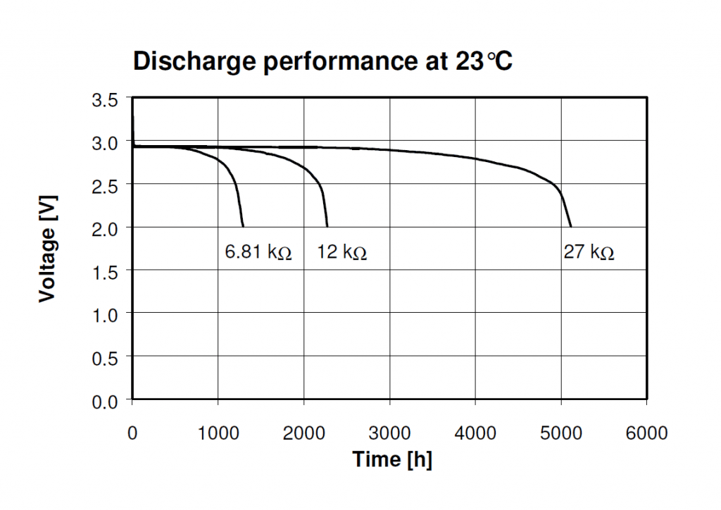
Since an RTC chip consumes very low current in the ranges of nano amperes, a coin cell is able to operate an RTC for a long time independent of a main supply. 3V Lithium coin cells are used for such applications. Lithum cells have long charge retentivity, up to 10 years.
Register Map
The register map gives all the details a programmer needs to write software for interfacing the RTC chip. Just like any other I2C devices, you can first send the slave address of the RTC followed by the register address you want to read or write. I have included all these addresses in the Arduino library. Note that, the RTC registers keep the values in BCD (Binary Coded Digits) format. So you need to convert to and from BCD when reading and writing those registers. The library also makes it easy to do this. Full description of the registers can be found on the datasheet.
Important Register Values
There are more functions available for the RTC than what I have included in my library. Such features can be configured easily if you know the registers. These are some of the important registers you might want to know about.
- WRTC : Write RTC Enable Bit should be set to
1if you want to access the registers. The default value is0. The RTC will not start counting until you reset this bit to1. The functionbegin()sets this bit to1when RTC is initialized. - RTCF : Real-time Clock Fail bit is read-only and is set to
1when both VDD and VBAT fall to 0V. So when you first power up the RTC, it will be1. It will be reset to0when you first write any of the registers. - ALM : Alarm Bit will be be set to
1when the alarm time matches the real-time clock. This is one way of determining the alarm condition. The other way is using the interrupt output from IRQ pin which will produce a 250ms signal at the same time the ALM bit is set.
Schematic
The ISL1208 needs very few external components to work. When using the IC on an actual application circuit, it’s a good practice to place a 0.1uF (100nF) power supply bypass capacitor closer to the VDD pin. The above schematic shows Arduino Nano as example. You can connect the RTC to I2C port of any of the Arduino boards. The R1 and R5 are common pull-up resistors for the I2C bus. For the battery backup, I have included the CR2450 3V Lithium cell which has a capacity of 540mAh and can easily run the RTC circuit for more than 10 years. For demonstrating the interrupt output, I have tied the IRG/FREQ pin of the RTC to digital pin 2 of the Arduino with interrupt capability. R3 is a pull-up for the interrupt pin but you can exclude this and use the internal pull-up instead.
Arduino Library
This library supports all official Arduino boards as well as other boards that have the Arduino core available such as ESP8266, ESP32, STM32 Nucleo etc.
Library Details
- Library version : 1.4.6
- Latest release : ISL1208-RTC-Arduino-Library-v1.4.6
- Author : Vishnu Mohanan
- Source : https://github.com/vishnumaiea/ISL1208-RTC-Library
- Initial release : IST 11:49:42 AM, 27-05-2018, Sunday
- Last updated : IST 09:07 PM 30-10-2019, Wednesday
- License : MIT
Installation
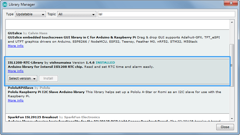
You can install the library from within the Arduino IDE itself. Open the library manager from Tools > Manage Libraries.. or press Ctrl+Shift+I. In the library manager search for “ISL1208” and install the latest version. The library folders and files will be added to your default folder. If you want to install it manually, go to the latest release page, where you can download the latest release as a ZIP file. Extract the contents to your default library folder and restart the Arduino IDE.
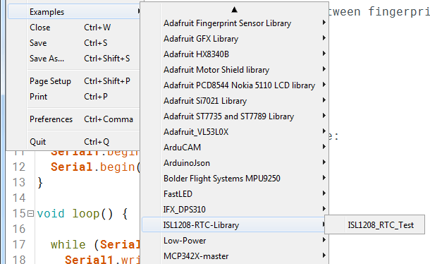
Once you have installed the library, you can open the example sketch from the Examples menu.
Dependencies
This library needs the following header files to work.
stdint.h
Arduino.h
Wire.h
Constants
All the constants are defined inside the main header file. It includes the RTC’s I2C slave address and the internal register addresses.
#define ISL1208_ADDRESS 0x6F  //I2C slave addess of RTC IC
#define ISL1208_SC      0x00  //seconds register
#define ISL1208_MN      0x01  //minutes register
#define ISL1208_HR      0x02  //hours register
#define ISL1208_DT      0x03  //date register
#define ISL1208_MO      0x04  //month register
#define ISL1208_YR      0x05  //year register
#define ISL1208_DW      0x06  //day of the week register
#define ISL1208_SR      0x07  //status register
#define ISL1208_INT     0x08  //interrupt register
#define ISL1208_ATR     0x0A  //analog trimming register
#define ISL1208_DTR     0x0B  //digital trimming register
#define ISL1208_SCA     0x0C  //alarm seconds register
#define ISL1208_MNA     0x0D  //alarm minutes register
#define ISL1208_HRA     0x0E  //alarm hours register
#define ISL1208_DTA     0x0F  //alarm date register
#define ISL1208_MOA     0x10  //alarm month register
#define ISL1208_DWA     0x11  //alarm day of the week register
#define ISL1208_USR1     0x12  //user memory 1
#define ISL1208_USR2     0x13  //user memory 2
Classes
The main class with variables and functions.
ISL1208_RTCMember Variables
These are public variables you can access using the object directly.
bool rtc_debug_enable; //enable this to get verbose output at serial monitor

byte yearValue;     //least significant digits of a year (eg. 18 for 2018, range is from 00 to 99)
byte monthValue;    //month (eg. 01 for January, range is 01 to 12)
byte dateValue;     //date (eg. 24, range is 01 to 31)
byte dayValue;     //date (eg. 3, range is 0 to 6)
byte hourValue;     //hours (eg. 06, range is 01 to 12 for 12 hour format)
byte minuteValue;   //minutes (eg. 55, range is 00 to 59)
byte secondValue;   //seconds (eg. 30, range is 00 to 59)
byte periodValue;   //period of the day for 12 hour format (0 = AM, 1 = PM)

byte monthValueAlarm;   //same as time values
byte dateValueAlarm;
byte dayValueAlarm;
byte hourValueAlarm;
byte minuteValueAlarm;
byte secondValueAlarm;
byte periodValueAlarm;

byte startOfTheWeek;   //starting day of week (eg. 3, range is 0 to 6)
byte tempByte;
Member Functions
ISL1208_RTC(); //constructor
void begin(); //alternate initializer
bool isRtcActive(); //checks if the RTC is available on the I2C bus
bool updateTime(); //update time registers from variables
bool setTime(String); //updates time registers from a formatted time string
bool updateAlarmTime(); //updates alarm registers from variables
bool setAlarmTime(String); //updates alarm registers from a formatted alarm time string
bool fetchTime(); //reads RTC time and alarm registers and updates the variables
int getHour(); //returns the 12 format hour in DEC
int getMinute(); //returns minutes in DEC
int getSecond(); //returns seconds value
int getPeriod(); //returns time period. 0 = AM, 1 = PM
int getDate(); //returns date
int getDay(); //returns day (0 to 6)
int getMonth(); //returns month (0 to 12)
int getYear(); //returns year (00 = 2000, 99 = 2099)
int getAlarmHour();
int getAlarmMinute();
int getAlarmSecond();
int getAlarmPeriod(); //0 = AM, 1 = PM
int getAlarmDate();
int getAlarmDay();
int getAlarmMonth();
String getTimeString(); //returns formatted time string (hh:mm:ss pp)
String getDateString(); //returns formatted date string (DD-MM-YYYY)
String getDayString(); //returns the full name of day
String getDayString(int n); //returns the first n chars of day string (n = 1 to 9)
String getDateDayString(); //returns a formatted date string with day name (DD-MM-YYYY DAY)
String getDateDayString(int n); //returns a formatted date string with n truncated day name
String getTimeDateString(); //returns a formatted time date string
String getTimeDateDayString(); //does what it says!
String getTimeDateDayString(int n); //returns a time, date string with n truncated day string
String getAlarmString();
bool printTime(); //prints time to the serial monitor
bool printAlarmTime(); //prints the alarm time to serial monitor
byte bcdToDec(byte); //converts a BCD value to DEC
byte decToBcd(byte); //converts a DEC value to BCD
Functions are explained below.
void begin();This is same as the default constructor. Use this to explicitly initialize the object. It resets all the time variables.
bool isRtcActive();This checks if the RTC is available on the I2C bus by reading the ACK signal. Returns true if RTC was found and false if it was not found on the bus.
bool updateTime();This updates the RTC time registers with the values present on the time variables available in the class. So if you want to set time, first save the values to the variables and then call this function.
bool updateTime(String);This updates the time from a single formatted time string. Useful in updating the time in a single command, for example from serial monitor. TYYMMDDhhmmssp# is the format for time string, where,
- T = indicates time information
- YY = least significant digits of a year (eg. 18 for 2018, range is from 00 to 99)
- MM = month (eg. 01 for January, range is 01 to 12)
- DD = date (eg. 24, range is 01 to 31)
- hh = hours (eg. 06, range is 01 to 12 for 12 hour format)
- mm = minutes (eg. 55, range is 00 to 59)
- ss = seconds (eg. 30, range is 00 to 59)
- p = period of the day for 12 hour format (0 = AM, 1 = PM)
- # = delimiter
For example, to set the time and date 08:35:12 AM, 05-01-2018, we should send: T1801050835120# where,
- T = indicates time information
- 18 = the year 2018
- 01 = month January
- 05 = date
- 08 = hours
- 35 = minutes
- 12 = seconds
- 0 = AM
- # = delimiter
bool updateAlarmTime();Updates the alarm registers with the variable values.
bool updateAlarmTime(String);Updates the alarm registers with a formatted string like we seen before. Format is AMMDDhhmmssp# where,
- A = indicates alarm information
- MM = month
- DD = date
- hh = hours
- mm = minutes
- ss = seconds
- p = time period (0 = AM, 1 = PM)
- # = delimiter
bool fetchTime();This function reads the RTC registers and updates all the variables including the alarm values. Returns true is the operation was a success, or false is the RTC was not found on the I2C bus.
int getHour();All these get functions first fetch the current time, update the time variables and return the data requested. So you don’t need to call fetchTime() every time. getHour() returns the hours in 12 hour format from 1 to 12 (DEC). 24 hour support will be added later.
int getMinute();Returns the minute value in DEC format.
int getSecond();Returns seconds in DEC format.
int getPeriod();Returns the time period when using 12 hour format. 0 = AM, 1 = PM
int getDate();Returns the date in DEC format.
int getDay();Returns the day value in DEC format. 0 = starting day of week, 6 = weekend
int getMonth();Returns month value in DEC format.
int getYear();Returns the year value in DEC format. The RTC actually stores only the two least significant digits of the year in BCD format; from 00 to 99. So 99 can be interpreted as 1999 or 2099. Both will be right because the calendars will be same for both centuries. This function interprets 00 as 2000 and 99 as 2099. I don’t know why you guys want to go to the past. May be you’re building a time machine or something?
int getAlarmHour();Returns the alarm hour value in DEC format.
int getAlarmMinute();Returns the alarm minute value in DEC format.
int getAlarmSecond();Returns the alarm seconds in DEC format.
int getAlarmPeriod();Returns the alarm time day period when 12 hour format is used. 0 = AM and 1 = PM.
int getAlarmDate();Returns the alarm date in DEC format.
int getAlarmDay();Returns the alarm day as a number between 0 to 6 where 0 = Sunday and 6 = Saturday.
int getAlarmMonth();Returns the alarm month as a number between 1 to 12 in DEC format.
String getTimeString();Returns a formatted time string in hh:mm:ss pp format.
String getDateString();Returns a formatted date string in DD-MM-YYYY format.
String getDayString();Returns the full length name of the day of the week, eg. Monday.
String getDayString(int n);Returns the first n characters of the day of the week where n can be 1-9. For example if the day is Monday and n=4, then the function will return a string “Mond”. Useful if you want shorthand versions of the day names.
String getDateDayString();Returns a formatted date string with full day of the week name, in DD-MM-YYYY DAY format.
String getDateDayString(int n);Returns a formatted date string in DD-MM-YYYY DAY format with day name truncated by n where n can be 1-9.
String getTimeDateString();Returns a formatted time-date string in hh:mm:ss pp, DD-MM-YYYY format.
String getTimeDateDayString();Returns a formatted time-date-day string in hh:mm:ss pp, DD-MM-YYYY DAY format.
String getTimeDateDayString(int n);Similar to the previous function but with day name truncated by n, where n can be 1-9.
String getAlarmString();Returns a formatted alarm time string in hh:mm:ss pp format.
bool printTime();Fetches current time from the RTC and prints it to the serial monitor. Returns true if the operation was success, or false if RTC could not be read.
bool printAlarmTime();Fetches currently set alarm time from the RTC and prints it to the serial monitor. Returns true if the operation was success, or false if RTC could not be read.
byte bcdToDec(byte);The RTC registers save values in BCD format. So we need to convert to and from BCD when we read or write the alarm registers. This function converts BCD values to DEC.
byte decToBcd(byte);This does the opposite.
Examples
Below is an example sketch to demonstrate some functions of this library. Upload it to your Arduino and open any serial monitor with a baudrate 115200.
ISL1208_RTC_Test.ino – https://github.com/vishnumaiea/ISL1208-RTC-Library/blob/master/examples/ISL1208_RTC_Test/ISL1208_RTC_Test.ino
The code is straightforward. When you first open the serial monitor, you’ll see the status message.
Then send a command with one or two parameters with each separated with a whitespace.
Testing
As I had an SMD version of the ISL1208, I made a small breakout board as shown below. I snatched the crystal from an old quartz clock’s PCB.
The current consumption of the ISL1208 in low power mode is only 400nA and at VDD is 1.2uA at max. So it’s good for portable applications that are battery powered. Having a wide range of voltage from 1.8-5V means, you can directly interface it with any microcontrollers that work on 5V such as some Arduino boards, or 3.3V ones such as STM32 Nucleo boards. This is for example, not possible with DS1307, because it needs a minimum supply voltage of 4.5V in order to access the registers via I2C, as per the datasheet. Therefore, ISL1208 is a better RTC than DS1307. An alternative option is the DS1308 which has a time-keeping current of 250nA which is better than ISL1208, but has no alarm feature which is a bummer.


