Interfacing Catalex Micro SD Card Module with Arduino
Tutorial on interfacing Catalex Micro SD card module with Arduino. Module pinout, wiring diagram, schematic and example code are included.
There will be times when you have to store a large amount of log data and other information for your Arduino project, for example, a GPS logger. The EEPROM memory of all available microcontrollers is limited in size. The solution is to use flash memories. Portable version flash memory is available as SD cards, in many capacities and form-factors. SD cards and USB flash drives have become indispensable things in our everyday life.
Even though you could insert an SD card in your phone or computer easily and browse all your files, hardware interfacing an SD card of any type with Arduino or similar development boards is not that easy. You could understand it just by reading the SD card spec sheet. The Secure Digital (SD) standard is maintained by the SD Card Association. They standardize and publish the necessary specifications to manufacture and implement SD cards. Most of the documents are confidential and are only available to manufacturers and software companies. A simplified version (it isn’t that simple) of the SD card specification is available for the public on the SD Card Association’s website.
What we’re going to do here is to interface a microSD card with an Arduino Uno using the SdFdat library developed by William Greiman and it is based on the Simplified SD Card Specification. Before we delve into interfacing, let’s have a basic understanding of what an SD card is, how it is organized, different forms and pinouts of it.
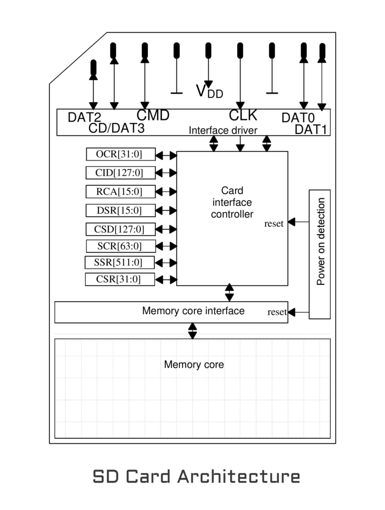
SD Card Architecture
The microSD card is a type of removable NAND-type small Flash memory card format which was introduced in 2003. Micro SD measures 11mm x 15mm and is 1mm thick. Internally the card is organized as interface driver, card interface controller, and memory core.
The interface driver connects to the external interface pins. This sets the pins to appropriate modes and selects and monitors the operating voltages and other parameters required for physical interfacing. The card interface controller is the section that processes user commands and reads from or writes to the actual memory core. It has many registers associated with it. The memory core is where data is stored. It is typically a NAND Flash memory.
Formatting
The SdFat library requires a properly formatted card to work. The library supports FAT16 and FAT32 file systems, though it is recommended to format to FAT16 when possible. You need a card reader and a PC to format the card. If you are on Windows 7, right-click the card volume icon and select the "Format" option. Now a window will open on which you have to select FAT or FAT16 from the drop-down list for the file system and then click "Start Format".
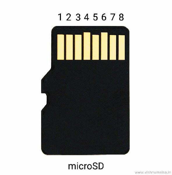
Micro SD Card Pinout
There are 8 pins on the micro SD card which you should avoid touching as you may damage the card with static electricity, even though it is protected against ESD. There are two ways a micro SD can be interfaced with a microcontroller – SPI mode and SD mode. The pin assignments for these modes are different. The SD mode is the fastest and is used in smartphones, digital cameras, etc. The Serial Peripheral Interface (SPI) mode is slow but requires less overhead compared to SD mode, and is compatible with any microcontroller with built-in SPI. We will use the SPI mode and its pin assignments.
| Pin | Pin Name | Function |
| 1 | NC | Not used |
| 2 | CS | Chip Select |
| 3 | COPI | Controller-out, Peripheral-in (MOSI) |
| 4 | VDD | Positive Supply |
| 5 | CLOCK | Serial Clock (SCK) |
| 6 | GND | Ground |
| 7 | CIPO | Controller-in, Peripheral-out (MISO) |
| 8 | NC | Not used |
Schematic of Catalex Micro SD Card Module
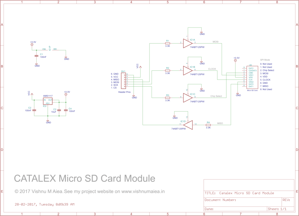
I bought the Catalex Micro SD Card Adaptors from Inkocean for Rs.70. Catalex is probably the brand or company name. I couldn’t find any datasheet or schematic for the module, and therefore I had to create one myself.
A micro SD card has an operating voltage of 3.3V. If your host board uses 3.3V as the logic supply (such as Arduino Due), then you do not need this module at all. Instead, you can directly interface the card to the microcontroller from the card slot. But if your microcontroller operates at voltages exceeding 3.3V, then you need a logic level shifter such as the module we’re discussing. This is because any voltages exceeding 3.6V can damage the SD card permanently.
The 741VC125 on the module is a quadruple 3-state buffer. It can translate the 3.3V logic signals from the card to and from a 5V Arduino Uno. We have to provide 3.3 – 3.6V as the supply voltage to the buffer in order for this to work. This is called logic level shifting. Three of the pins, COPI, SCK and CS carry signals from the Arduino to the card and the CIPO carries signals from the card to Arduino. Therefore one of the buffers is connected in reverse order (see the IC1D part in the above schematic). All four buffers have 3.3K resistors in series for protection.
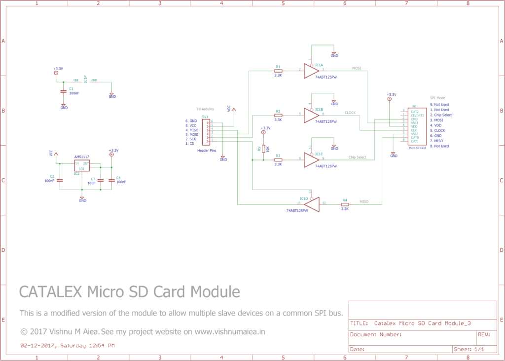
But there is another problem; as the ENABLE pin 13 (CIPO) of the buffer of 74VC125 is always tied to GND. Other peripherals, if using multiple peripherals on the same SPI bus, cannot communicate with the host controller as the signals will interfere with each other. Peripherals actually need to activate high impedance state on the CIPO pin when not selected on a common SPI bus. Therefore to use other SPI peripheral devices along with this module, you need to make some small changes. First, disconnect pin 13 of the buffer from GND and then tie it to the respective CS pins of the host device, probably with a pull-up. This way, the CIPO of the module will be brought to high-impedance state when it is not selected. Thanks to Christian Charlot for pointing out this issue. Below is a modified schematic to allow multiple SPI peripherals on the common SPI bus.
Wiring with Arduino Uno
Even though the micro SD card has 8 pins, we need only 6 pins to interface it using SPI and therefore have 6 header pins soldered on the module. There are two supply pins – VCC and GND. VCC is connected to 5V and the on-board low drop regulator AMS1117 will provide 3.3V to the card and the buffer IC 74LVC125. The CIPO, COPI, and SCK (Serial Clock) are connected to the respective pins of the microcontroller. The CS (Chip Select) is connected to the CS of the microcontroller. In fact, you can use any digital pins to connect to the module and bit-bang the SPI protocol. But it would be better to use the hardware SPI for a few reasons. I have provided a wiring schematic below and to make it easy for you, the wiring procedure in multiple steps too. If you’re using another Arduino model, just use the respective pins. Connect,
- VCC of module to 5V of Arduino.
- GND of module to GND of Arduino.
- CS to digital pin 10 of Uno.
- COPI to digital pin 11 of Uno.
- CIPO to digital pin 12.
- SCK to digital pin 13.
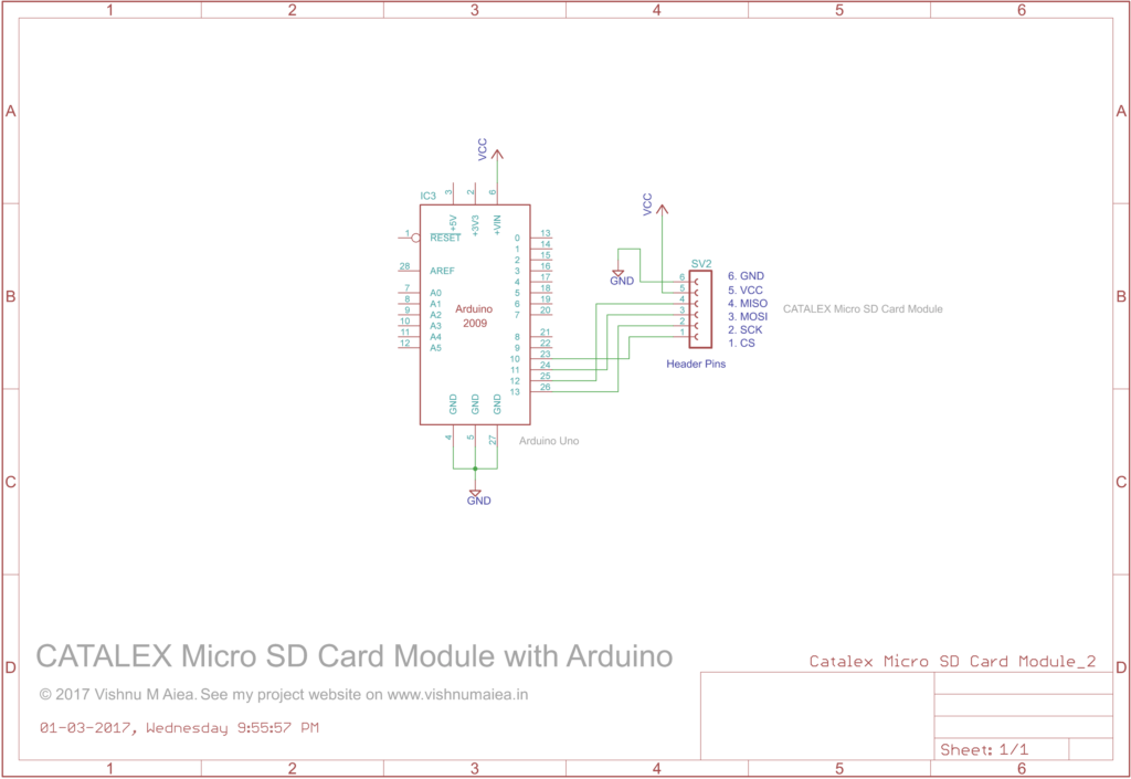
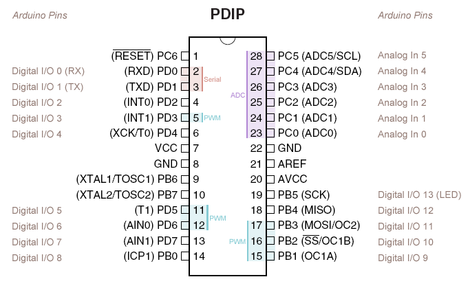
In Arduino Uno, the digital pin 10 (pin 16 of ATmega328P) is the dedicated CS pin. But you could connect the CS of the module to any digital pin of the Uno by initiating the card with SD.begin(pin). The SdFat library needs the digital pin 10 (CS pin on Arduino) to set as output because the CS will be still manipulated when hardware SPI is used. So changing its state to digital output might disable the SPI. There will be usually a Chip Detect (CD) pin from the SD card slot. But unfortunately, the module we are using doesn’t have a CD output. That’s all about the wiring. Here is a pinout of an ATmega8/168/328 if you feel confused.
For using the module with 3.3V devices, all you need to do is to bypass the onboard 3.3V regulator and connect your 3.3V supply to the output pin of the regulator (or you can remove the regulator too). The 74LVC125 works fine with a 3.3V supply.
Code
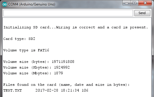
If you have connected the module with Arduino, now we can upload the code to read the card information. The program is available from the example library in the Arduino IDE. Go to File > Examples > SD > CardInfo. Now the program will be opened in a new window. On the 36th line, change the value of chipSelect from 4 to 10, if you had connected the module as we said earlier. Otherwise, set it to the pin you chose. Then compile and upload. If everything was done correctly, you can see the card information printed when you open the serial monitor.
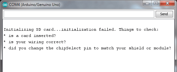
If nothing shows up, chances are you did the wiring wrong. Go back and check if everything is done right. If wiring is right and the card you inserted is faulty, then an “initialization failed” message will be printed along with some troubleshooting tips.
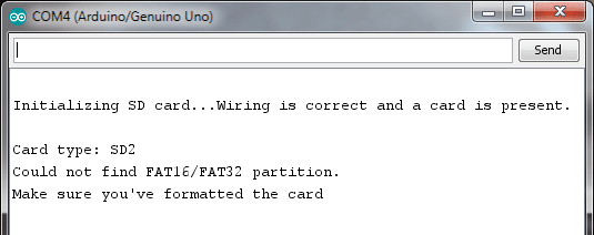
If the wiring is right and the card is well formatted to FAT16 or FAT32, then the program will print the card details and list of files present in it. If the SD card is not properly formatted, the following message will show up.
As I mentioned earlier, we are using the SdFat library from William Greiman. The Arduino IDE comes with the SD library preinstalled. That means, all you have to do to use the library is to include the SD.h file in your code. The SD library is well documented in the reference section of Arduino website. Head over to there and read about the available classes, functions and their return types. The CardInfo.ino program uses some utility functions that are not documented in there. You can find those information and more in the GitHub page of the SdFat library. The repository contains an HTML documentation.
I have written some code to initialize, write to and read from the SD card through simple serial commands. This would help you to be conscious of what happening rather than just opening the serial monitor and seeing everything printed automatically. The following code initializes the card when you type and send the command i.
// -----------------------------------------------------//
//
//  Micro SD Card initialization code.
//  Type "i" or "I" in the serial terminal to
//  initialize the card.
//
//  Author : Vishnu M Aiea
//  Web : www.vishnumaiea.in
//  IST 4:04 PM 28-02-2017, Tuesday
//
//------------------------------------------------------//

#include <SPI.h>
#include <SD.h> //include the SD library
byte inByte;
bool sdInitSuccess = false; //card init status

void setup() {
  Serial.begin(9600);
  while (!Serial) {
    ; //wait for the serial port to connect.
  }
}

void loop() {
  if (Serial.available() > 0) {
    inByte = Serial.read();
    if (inByte == 'i' || inByte == 'I') {
      if (sdInitSuccess) {
        Serial.println("Already initialized.");
        Serial.println();
      }
      else if (!sdInitSuccess) { //if not already initialized
        Serial.println("Initializing SD Card..");
        if (!SD.begin(10)) { //using pin 10 (CS)
          Serial.println("Initialization failed!");
          Serial.println();
          sdInitSuccess = false;
          return;
        }
        else {
          Serial.println("Intitialization success.");
          Serial.println();
          sdInitSuccess = true;
        }
      }
    }
  }
}
The code is self-explanatory. It first establishes serial communication link with a baud rate of 9600 when the microcontroller turns on. The card gets initialized when you type and send i or I from the serial monitor. It will print whether the initialization was success or not. You can not initialize a card that is already initialized. You have to break the serial communication link to do that.
Below is a code that will initialize the card, open a text file called TEST.txt, create if there isn’t one, write a piece of text to the file, read and print from the file. Type i to initialize, n to open/create a text file and r to read and print from the file via serial monitor. There is one thing to be aware of : file naming convention. You can not have files named like I Have Some File Here.txt. Because the SD Card library only supports the 8.3 or Short File Name convention. As per SFN scheme, the file name must be of maximum 8 characters + a period + three character extension (thus the 8.3) and the name is not case sensitive.
Tap to expand the code.
Example code : Writing to and reading from a micro SD card.
//---------------------------------------------------------------//

//  Writing to and reading from a micro SD card.
//
//  Type "i" or "I" in the serial terminal to
//  initialize the card.
//
//  Type "n" to open/create a new file and
//  write to it.
//
//  Type "r" to read some text until a \n
//
//  Author : Vishnu M Aiea
//  Web : www.vishnumaiea.in
//  IST 7:22 PM 28-02-2017, Tuesday

//---------------------------------------------------------------//

#include <SPI.h>
#include <SD.h>
byte inByte; //byte read from terminal
bool sdInitSuccess = false; //card init status
File myFile;
String readText; //text read from file
char readCharArray[128]; //buffer for reading from file
unsigned long fileSize; //size of opened file
unsigned long filePos = 0;

//---------------------------------------------------------------//

void setup() {
  Serial.begin(9600);
  while (!Serial) {
    ; //wait for the serial port to connect.
  }
}

//---------------------------------------------------------------//

void loop() {
  if (Serial.available() > 0) {
    inByte = Serial.read();
    if (inByte == 'i' || inByte == 'I') {
      if (sdInitSuccess) { //check if card is initialized already
        Serial.println("Already initialized.\n");
      }
      else if (!sdInitSuccess) { //if not already initialized
        Serial.println("Initializing SD Card..");
        if (!SD.begin(10)) { //using pin 10 (SS)
          Serial.println("Initialization failed!\n");
          sdInitSuccess = false; //failure
          return;
        }
        else {
          Serial.println("Intitialization success.");
          Serial.println();
          sdInitSuccess = true;
        }
      }
    }
    else if (inByte == 'n' || inByte == 'N') {
      if (sdInitSuccess) { //proceed only if card is initialized
        myFile = SD.open("TEST.txt", FILE_WRITE);
        if (myFile) {
          Serial.println("File opened successfully.");
          Serial.println("Writing to TEST.text");
          myFile.println("Line 1");
          myFile.close(); //this writes to the card
          Serial.println("Done");
          Serial.println();
        }
        else { //else show error
          Serial.println("Error opeing file.\n");
        }
      }
      else {
        Serial.println("SD Card not initialized.");
        Serial.println("Type \"i\" to initialize.\n");
      }
    }
    else if (inByte == 'r' || inByte == 'R') {
      if (sdInitSuccess) { //proceed only if card is initialized
        myFile = SD.open("TEST.txt");
        if (myFile) {
          Serial.println("File opened successfully.");
          Serial.println("Reading from TEST.text");
          readText = (String) readUntil(myFile, 10); //read until newline
          Serial.print(readText);
          Serial.print(", ");
          Serial.println(filePos); //print current file position
          Serial.println();
          myFile.close();
        }
        else {
          Serial.println("Error opening file.\n");
        }
      }
      else {
        Serial.println("SD Card not initialized.");
        Serial.println("Type \"i\" to initialize.\n");
      }
    }
    else {
      Serial.println("Not recognized.\n"); //unknown cmd
    }
  }
}

//--------------------------------------------------------------//

String readUntil(File &myFile, char n) { //read until n
  int i = 0;
  myFile.seek(filePos); //read from current filepos

  do {
    if (myFile.peek() != -1) { //check if file is empty
      readCharArray[i++] = myFile.read(); //read otherwise
      filePos++; //advance the filepos
    }
  } while ((myFile.peek() != -1) && (readCharArray[i - 1] != n)); //if not eof | \n
  if (myFile.peek() == -1) { //if eof reached
    filePos = 0; //if eof, reset to start pos
  }
  readCharArray[i - 1] = '\0'; //remove the extra \n
  return readCharArray;
}

//-------------------------------------------------------------//
I have thoroughly commented the code. So I hope you wouldn’t find it hard to understand. The card is initialized just like we saw in the previous program. The boolean variable sdInitStatus keeps track of the card initialization status. The file is opened with write mode when you enter n and if there is no file with that name, the write mode will cause a file to be created and then opens it; just like in the C/C++ file handling programs. An object of type SD is used in conjunction with the println() function to write to the file. Note that data is written to the file only when the functions close() or flush() is invoked. Make sure to do that right when you write a program for any application.
The r command will open the file we just created with read mode which is the default one. You can use the read() function to read a single byte from the file. The read function will return -1 if the file is empty or the EOF (End of File) is reached. The current position within the file is incremented by 1 when you read a single byte using the read() function. We keep track of the file position using the variable filePos. The file position can be obtained using the position() function. The maximum value of file position will be the size of the file which can be obtained by calling size().
Here we are using a separate function to read any text from the file until a newline character (\n whose DEC equivalent is 10) is found or the EOF reached. The function uses peek() to determine the end of file which returns a -1 at EOF. Unlike read(), the peek() doesn’t increment the actual file position after execution. The seek() function sets the file position to desired point in file. We have used this to relocate the file position to the start of the file when EOF is found so that we can read the file again.
Text is read to a char array readCharArray[] and then converted to String type using type casting.
Now you know how to include a Micro SD card in your next Arduino project and learned what the SD card library can and can’t do. I hope you enjoyed reading this tutorial and learned something new. If you found any error with the descriptions, code or missed something important, however small it is, please feel free to inform me. Thanks for reading.

