Reading Push-Buttons Through Interrupt : Learn Microcontroller with STM8S – Tutorial Part #7
In the last tutorial, we learned how to read a push-button using the polling method. While it is a simple method to implement, it comes with a huge drawback of blocking critical code and wasting the time of our CPU. Similar to how we have used interrupts to blink the LED, we can also use interrupts to read push-buttons without blocking code. In this post, we will see how to use the external interrupt functionality of the STM8S microcontroller to implement this using the assembly language. The circuit and parts you need to follow this tutorial remain the same as before.
Reading Push-Buttons Through Polling : Learn Microcontroller with STM8S – Tutorial Part #6
Tutorial Series
- Learn the fundamentals of microcontrollers.
- Familiarize with a simple STM8S microcontroller.
- Install all the software tools and prepare your computer for programming and debugging microcontrollers.
- Get hands on experience with connecting your first microcontroller board and write a program for it.
- Learn the concepts of timers and interrupts in microcontrollers and blink an LED with what you learn.
- Learn how to make your microcontroller interact with the world by reading a push-button.
- Learn how to read a push-button using external interrupts without blocking critical code.
What You’ll Learn
- What are external interrupts in a microcontroller.
- How to read a push-button with the help of external interrupts.
- How to configure STM8S external interrupts.
External Interrupts
We already learned about how interrupts can be used to run tasks asynchronously by using the timer interrupts of STM8S to blink an LED. We can also use interrupts in response to state changes to a GPIO pin. The interrupt generated by the internal timer of a microcontroller is a category of interrupts known as a Peripheral Interrupt. Such interrupts are generated by internal peripherals and detected by the CPU core. But interrupts do not have to origin internally but can also be external. Such interrupts are called External Interrupts and can be used with the GPIO pins. Following are the list of pins of STM8S microcontroller external interrupt GPIO pins.
- 5 lines on Port A:
PA [6:2] - 8 lines on Port B:
PB [7:0] - 8 lines on Port C:
PC [7:0] - 7 lines on Port D:
PD [6:0] - 8 lines on Port E:
PE [7:0]
You can program the microcontroller to generate an interrupt when the state of the GPIO pin changes. You can adjust the interrupt sensitivity of the interrupt to the following states.
- Falling edge only
- Falling edge and
LOWlevel - Rising edge only
- Rising and falling edges

A Rising edge is simply a transition of voltage from LOW to HIGH. In the case of the STM8S microcontroller with a 3.3V supply, the HIGH level is 3.3V and the LOW level is close to 0V. A Falling edge on the other hand is a transition from HIGH level to LOW level. STM8S external interrupt pins support both edges and state changes which is very convenient to integrate external devices like puh-buttons. PD7 is the Top Level Interrupt source (TLI), except for 20-pin packages on which the TLI can be available on the PC3 pin using an alternate function remapping option bit. To generate an external interrupt, the GPIO pin should be set to Input mode with the interrupt sensitivity properly configured. If you wish to refresh your knowledge about interrupts, this is a good time. Check out the Interrupts section in the Part #5 of this tutorial series.
There are two dedicated external interrupt configuration registers in addition to the already discussed CCR (Condition Code Register) and ITC_SPRx (Software Priority Register) registers. These are EXTI_CR1 (External Interrupt Control Register 1) and EXTI_CR2 (External Interrupt Control Register 2).
EXTI_CR1
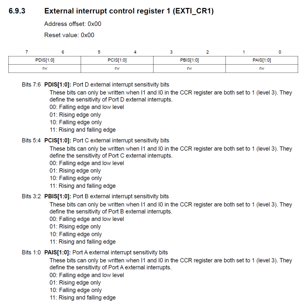
EXTI_CR1 register descriptionThis register sets the interrupt sensitivity of the GPIO ports from A to D. These bits can be only written when the CCR register’s I0 and I1 are at 1 (the default value). When an interrupt occurs, the interrupt priority of the current interrupt is automatically loaded from the corresponding ITC_SPRx register to the CCR register.
EXTI_CR2
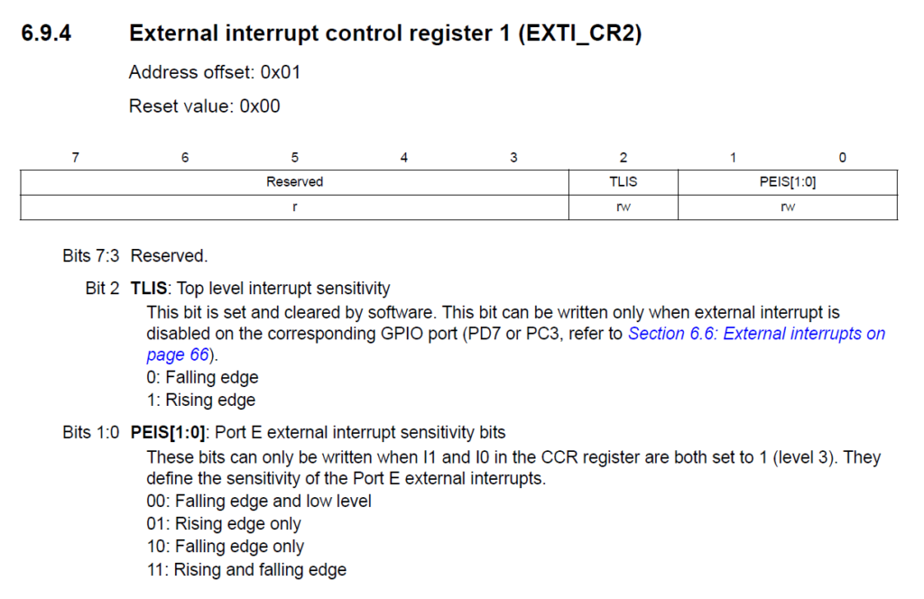
EXTI_CR1 register descriptionThis register configures the Port E interrupt sensitivity and the interrupt sensitivity of the TLIS.
Code
Everything is better explained through code. Here, will use a similar code to our polling-based Blink program. But now, instead of using polling, we will use external interrupts. The algorithm is as follows.
- Set the LED pin to a push-pull output so that we can drive it
LOWandHIGH. - Set the Push-Button pin to an input with no internal pull-up. This will leave the pin as floating. We need an external pull-up or pull-down for setting a state. We will use a pull-up.
- Set the interrupt level of the push-button pin to detect a falling edge signal only.
- Update the priority of external interrupt priority of Port B to Level 1.
- Enable the interrupts.
- Enable low-power sleep mode and wait for an interrupt to occur.
- When the push-button is pressed (creating a falling-edge), blink the LED twice and go to sleep mode again.
We can expand the algorithm with finer details to better structure the program. You can also create a flow-chart based on it. But when you write an algorithm for the first time for any complex projects, keep it as simple as possible. Now check the code.
.stm8

; STM8 Naken-ASM Assembly Program:
; LED blinking on a push-button interrupt
; Author: Vishnu Mohanan (@vishnumaiea)
; Version 0.1

;---------------------------------------------------------------------------------;

.include "stm8s103.inc"

F_CPU           EQU   16000000  ; CPU clock frequency, required by delay routines
DELAY           EQU   100       ; Blink interval in ms

; CLK_CKDIVR flags
HSIDIV_00       EQU   0x00      ; HSI prescaler: fHSI / 1
CPUDIV_000      EQU   0x00      ; CPU prescaler: fMASTER / 1

LED             EQU   5         ; LED pin index on Port B (B5)
BUTTON          EQU   4         ; Push-button pin on Port B (B4)

.org RAM_START                  ; Where variables are stored
counter:    .db 0x00

.org CODE_START                 ; Where the code starts

;---------------------------------------------------------------------------------;
; Main program body.

start:
    SIM                         ; Disable interrupts

    MOV     CLK_CKDIVR, #(HSIDIV_00 | CPUDIV_000)  ; clock setup

    BSET    PB_DDR, #LED        ; Set the LED pin as output
    BSET    PB_CR1, #LED        ; Set the LED pin as push-pull
    BSET    PB_ODR, #LED        ; Set the LED output to LOW initially

    BRES    PB_DDR, #BUTTON     ; Set the push-button pin as input
    BRES    PB_CR1, #BUTTON     ; Set the CR1 bit to 0 to disable the pull-up
    BSET    PB_CR2, #BUTTON     ; Set the CR2 bit to 1 to enable the interrupt

    BRES    EXTI_CR1, #2        ; Set PBIS.0 to 0
    BSET    EXTI_CR1, #3        ; Set PBIS.1 to 1

    ; Set the interrupt prioroty of EXTI1 (Port B) to 01 (Levl 1)
    BSET    ITC_SPR3, #0
    BRES    ITC_SPR3, #1

    ; ; Set the interrupt prioroty of EXTI1 (Port B) to 00 (Levl 2)
    ; BRES    ITC_SPR3, #0
    ; BRES    ITC_SPR3, #1

    ; ; Set the interrupt prioroty of EXTI1 (Port B) to 11 (Levl 3)
    ; BSET    ITC_SPR3, #0
    ; BSET    ITC_SPR3, #1

    RIM                         ; Enable interrupts

;---------------------------------------------------------------------------------;
; This function puts the MCU to sleep mode until an interrupt occurs.

loop:
    WFI                         ; Wait for an interrupt
    JP      loop                ; Loop forever

;---------------------------------------------------------------------------------;
; Function to blink the LED when the push-button interrupt is generated.

.func pb_isr
    JP      blink_led           ; Blink the LED
    IRET                        ; Return from the ISR
.endf

;---------------------------------------------------------------------------------;
; Function to blink the LED two times.

.func blink_led
    LD      A, #4
    LD      counter, A
    loop:   ; Example for a label with local scope
        LDW     X, #DELAY       ; Load the blink interval
        BCPL    PB_ODR, #LED    ; Toggle the LED pin
        CALL    delay_ms        ; Wait for the DELAY ms
        DEC     counter
        JRNE    loop
    RET
.endf

;---------------------------------------------------------------------------------;
; Function to create delays in multiple of a millisecond.

.func delay_ms
loop_ms:
    LDW     Y, #((F_CPU / 1000) / 3)    ; Set the inner loop to the equivalent of 1000 us

loop_cycles:
    DECW    Y                   ; Decrement the inner loop
    JRNE    loop_cycles         ; Loop until Y is zero
    DECW    X                   ; Decrement the number of milliseconds
    JRNE    loop_ms             ; Loop until X is zero
    RET
.endf

;---------------------------------------------------------------------------------;
; Interrupt vectors

.org VECTORS_START
    INT     start       ; RESET handler, jump to the main program body

.org 0x8018
    INT     blink_led   ; EXTI1: Port B external interrupt

;---------------------------------------------------------------------------------;
Uploading
We will upload the code and run it before explaining it. You can assemble the programs using the following command, just like we always do.
naken_asm main.asm -o main.hex -type hex -lAssembling the interrupt-based code generates the following output. The number of bytes needed here is definitely higher since we have more instructions.
PS D:\Code\Naken-ASM\STM8\Push-Button-Interrupt> naken_asm main.asm -o main.hex -type hex -l

naken_asm

Authors: Michael Kohn
         Joe Davisson
    Web: https://www.mikekohn.net/
  Email: mike@mikekohn.net
Version:

 Input file: main.asm
Output file: main.hex
  List file: main.lst

Pass 1...
Pass 2...

Program Info:
Include Paths: .
               /usr/local/share/naken_asm/include
               include
 Instructions: 33
   Code Bytes: 93
   Data Bytes: 2
  Low Address: 0x0000 (0)
High Address: 0x80d4 (32980)Following is the hex file generated after assembling.
:020000000000FE
:0480000082008080FA
:04801800820080B6AC
:108080009B350050C6721A5007721A5008721A5067
:10809000057219500772195008721850097215505C
:1080A000A0721650A072107F7172137F719A8FCCDC
:1080B00080AECC80B680A604B700AE0064901A50A3
:1080C00005CD80C93A0026F28190AE14D5905A268B
:0580D000FC5A26F581B9
:00000001FF
Uploading is a little different here, as we have seen before. Because we have variables stored in the data space (RAM), NakenASM will also include the data space in the generated hex file. But the STMFlasher tool can not access this area through the debugger during programming. Therefore, we need to delete the data section from the hex file before we can upload it to the microcontroller. If you try to upload without fixing the hex file, you will get an error like shown below.
PS D:\Code\Naken-ASM\STM8\Push-Button-Interrupt> stm8flash -c stlinkv2 -p stm8s003f3 -w main.hex
Determine FLASH area
libusb: error [init_device] device '\\.\USB#VID_1532&PID_0099&MI_03#6&3475DE72&0&0003' is no longer connected!
libusb: warning [force_hcd_device_descriptor] could not infer VID/PID of HCD hub from '\\.\ROOT#USB#0000#{3ABF6F2D-71C4-462A-8A92-1E6861E6AF27}'
libusb: warning [force_hcd_device_descriptor] could not infer VID/PID of HCD hub from '\\.\ROOT#USB#0000#{3ABF6F2D-71C4-462A-8A92-1E6861E6AF27}#UDE'
libusb: error [init_device] device '\\.\USB#VID_046D&PID_0825&MI_02#8&1DF2C811&0&0002' is no longer connected!
Due to its file extension (or lack thereof), "main.hex" is considered as INTEL HEX format!
Address 0000 is out of range at line 1As we did last time, we need to delete the first line, after which we get the following file.
:0480000082008080FA
:04801800820080B6AC
:108080009B350050C6721A5007721A5008721A5067
:10809000057219500772195008721850097215505C
:1080A000A0721650A072107F7172137F719A8FCCDC
:1080B00080AECC80B680A604B700AE0064901A50A3
:1080C00005CD80C93A0026F28190AE14D5905A268B
:0580D000FC5A26F581B9
:00000001FF
After removing the first lines, you will be able to upload them with the following command.
stm8flash -c stlinkv2 -p stm8s003f3 -w main.hexAfter uploading, you can try pressing the button. The red LED on the board will flash twice and stop. Some times, the LED will also blink when you just release the button. This happens due to an mechanical effect inherent to dome switches called bouncing. The push-button has a metal dome inside which is compressed when you press the button. But unlike you imagine, the dome will not be compressed in one go. Instead, it oscillates up and down before settling to the fully-compressed state. This will generate not just one falling-edge but many rising and falling edges in a quick succession. Since the microcontroller processes the interrupts very fast, sometimes it catches these additional falling-edges and trigger an interrupt. Switch bouncing can be problematic in practical applications. There are ways to fix this issue, either using hardware or software or a combination of both and it is called debouncing.
Code Explained
The following part is already familiar to you. We are defining few constants here to be later used in the program. For the LED, we are using the GPIO5 of Port B. For the push-button, we are using GPIO4 of Port B.
.include "stm8s103.inc"

F_CPU           EQU   16000000  ; CPU clock frequency, required by delay routines
DELAY           EQU   100       ; Blink interval in ms

; CLK_CKDIVR flags
HSIDIV_00       EQU   0x00      ; HSI prescaler: fHSI / 1
CPUDIV_000      EQU   0x00      ; CPU prescaler: fMASTER / 1

LED             EQU   5         ; LED pin index on Port B (B5)
BUTTON EQU 4 ; Push-button pin on Port B (B4)Since the variables are stored in the RAM, we are setting the start of the RAM memory address at 0x0000. RAM_START is a constant defined in the stm8s103.inc include file. counter is a variable of byte type and only occupy a single byte in the memory. The value is initialized to 0x00.
.org RAM_START                  ; Where variables are stored
counter: .db 0x00 In the following line, we are defining the start of the program storage. This is nothing different from the examples we learned in the previous tutorials. This time, we are simply using the constant defined in the include file. You should now understand the usage of such constants completely. An advantage of this style of writing is a program is that we can port the code to other microcontrollers whose code space address might be different. Since we are not using a hard-coded value, the definition can be easily changed.
.org CODE_START ; Where the code startsSince our program uses interrupts, the first thing to do is to disable all interrupts initially. This allows us to configure the interrupts without worrying it being interrupted. After configuring everything we will re-enable the interrupts. We are also setting the clock divider here because we need to create delays for blinking the LED.
start:
    SIM                         ; Disable interrupts

MOV CLK_CKDIVR, #(HSIDIV_00 | CPUDIV_000) ; clock setupIn the next three lines, we are configuring the LED pin. We can make the GPIO pins an output by writing the DDR register bit to 1. To drive the pin LOW and HIGH from the program, we need to make the output type push-pull. This can be done by writing to the control register CR1 of Port B. Since we do not want the LED to turn on initially, we will pull the pin LOW by writing a 1 to the pin. Since the GPIO pin is connected to the Cathode (K) of the LED, this will turn off the LED.
BSET    PB_DDR, #LED        ; Set the LED pin as output
BSET    PB_CR1, #LED        ; Set the LED pin as push-pull
BSET PB_ODR, #LED ; Set the LED output to LOW initiallyIn the following three lines, we are configuring the GPIO pin connected to the push-button. The other end of the push-button is connected to GND. When we press the push-button, the GPIO pin is connected to the GND. To set the GPIO pin as input, we can write a 0 to the DDR register. Since we have an external pull-up already, we are disabling the internal pull-up by writing a 0 to the CR1 register. If you do not have a resistor to pull-up the pin externally, you can enable the internal pull-up instead. The last line is interesting. We are enabling the external interrupt on the GPIO pin by writing to the corresponding bit on the CR2 register.
BRES    PB_DDR, #BUTTON     ; Set the push-button pin as input
BRES    PB_CR1, #BUTTON     ; Set the CR1 bit to 0 to disable the pull-up
BSET PB_CR2, #BUTTON ; Set the CR2 bit to 1 to enable the interruptWe already know that not all GPIO pins support external interrupts. Following is a list of interrupt supported pins on each port.
- 5 lines on Port A:
PA [6:2] - 8 lines on Port B:
PB [7:0] - 8 lines on Port C:
PC [7:0] - 7 lines on Port D:
PD [6:0] - 8 lines on Port E:
PE [7:0]
Each of these interrupts have 5 interrupt vectors in STM8S103F3P6 as shown below.
| IRQ # | Name | Description | Wakeup from Halt mode | Wakeup from Active-Halt mode | Vector Address |
|---|---|---|---|---|---|
| 3 | EXTI0 | Port A external interrupts | Yes | Yes | 0x00 8014 |
| 4 | EXTI1 | Port B external interrupts | Yes | Yes | 0x00 8018 |
| 5 | EXTI2 | Port C external interrupts | Yes | Yes | 0x00 801C |
| 6 | EXTI3 | Port D external interrupts | Yes | Yes | 0x00 8020 |
| 7 | EXTI4 | Port E external interrupts | Yes | Yes | 0x00 8024 |
Since each of the five interrupt vectors are common to a specific port, external interrupts occurring on the any pins of the port must be served by the same ISR. When we enable the external interrupt on GPIO B4, the ISR will be called from the EXTI1 location.
In addition to enabling the interrupt functionality on a GPIO pin, we also need to set the type of interrupt by configuring the EXTI_CR1 configuration register. As you can see, we can configure for each port by writing just two bits.
Since we are using Port B here, we can set to only detect falling edges by writing a 0b10 which is achieved with the following two lines.
BRES    EXTI_CR1, #2        ; Set PBIS.0 to 0
BSET EXTI_CR1, #3 ; Set PBIS.1 to 1Configuring interrupts is not over yet. Remember when we said STM8 microcontrollers support different interrupt priorities? There are four interrupt priorities in the STM8, from Level 0 to Level 3. Level 0 is the default. When we don’t set any priorities explicitly, Level 0 is assumed. Level 0 is also can not be set manually. For this example, we will set the priority to Level 1 by writing 0b01 to the VECT4SPR [1:0] (bit position 0 and 1) of the ITC_SPR2 register.
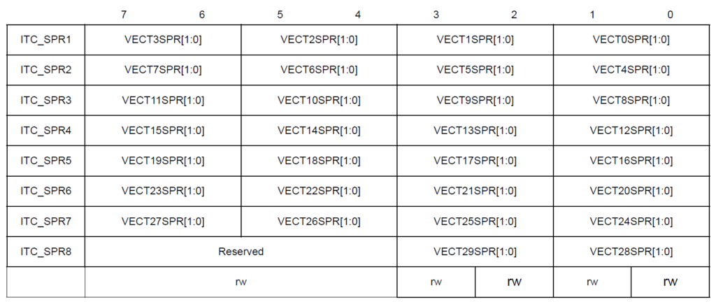
This is done with the help of following two lines.
; Set the interrupt prioroty of EXTI1 (Port B) to 01 (Levl 1)
BSET    ITC_SPR2, #0
BRES ITC_SPR2, #1If this doesn’t make sense yet, you just need to look at the IRQ number of the external interrupt vector EXTI1 associated with Port B. As you have noticed, it is 4 and therefore we need to set the interrupt priority at VECT4SPR [1:0]. Even if you do not set the priority here, the interrupts will still work but with a side effect. The LED will repeatedly blink when you press and hold the button. Can you try explaining why?
With that we can finish configuring everything. As a last step, we can enable the interrupts by calling the RIM instruction.
RIM ; Enable interruptsThe loop section is the same as our previous example. It puts the microcontroller in a low-power sleep mode until an interrupt occurs. If it was the timer overflow interrupt in the previous example, here it is going to be the falling-edge generated by a push-button.
; This function puts the MCU to sleep mode until an interrupt occurs.

loop:
    WFI                         ; Wait for an interrupt
JP loop ; Loop foreverWe always need a special interrupt service routine (ISR) to process interrupts when they happen. The following function pb_isr will handle the interrupt from the push-button. As soon as we press the push-button, this function is invoked. The first instruction is a jump call to a label called blink_led. It is a section of the program that blinks the LED twice. So every time we press the button, the LED blinks twice. IRET is a special instruction to return from an ISR. This is different from the regular RET instruction.
; Function to blink the LED when the push-button interrupt is generated.

.func pb_isr
    JP      blink_led           ; Blink the LED
    IRET                        ; Return from the ISR
.endfThe following function to blink the LED is similar to the previous example, but with some differences. Instead of using the X index register to set the time delay we need, we are using the variable counter stored in the RAM. The reason is that the X and Y index registers are already used for controlling the delay function. So we can not use them anywhere else right now. When we can not use the CPU registers everywhere, we resort to variables stored in the RAM. Even though RAM is slower than hardwired CPU registers, for our example, it is still fine.
; Function to blink the LED two times.

.func blink_led
    LD      A, #4
    LD      counter, A
    loop:   ; Example for a label with local scope
        LDW     X, #DELAY       ; Load the blink interval
        BCPL    PB_ODR, #LED    ; Toggle the LED pin
        CALL    delay_ms        ; Wait for the DELAY ms
        DEC     counter
        JRNE    loop
    RET
.endfWe initialized the counter variable with 0x00. We now have to load the variable with the value we need which is 4. In order to blink an LED twice, we need two ON times and two OFF times. We need to generate the delay four times. We will keep track of the number of delays using the counter variable. To load the value to the variable we are using the LD instruction. It can load a byte value to a memory location or a register. The value can be immediate or from a register or memory. We are using an immediate value of #4 here.
We are loading the value first to the A register. After that, we can load the value in A to the counter variable. This is the only way we can load a value to the counter variable.
In the loop section, we will execute a few instructions repeatedly. This loop label is different from the loop label we saw before. Since this loop label appears inside the function, it has a local scope. That means, calling the loop label inside the function will call the local label instead of the one outside. After loading the delay value, toggling the LED, we can call the blocking delay function. In the next line, we will use the instruction DEC to decrement the value at the counter variable. Since the initial value of counter is 4, after the first iteration, the value will become 3. The next instruction JRNE checks the status of the last instruction and if it is not 0, jumps to the given label. In this case, it causes the CPU to execute the set of instructions again. When the value of the counter variable becomes 0, JRNE will evaluate to true and thus exit from the loop. The effect of this will be that the LED will blink two times, which is what we just need. Since the function will be over by now, a RET instruction causes the function to return to the previous point, which is the pb_isr function.
Once the pb_isr also returns, there will be silence. The CPU will again go to sleep mode, waiting for the next interrupt. If you press the push-button again and again, the LED will blink each time. If you keep pressing the button, the LED will blink twice and stop. If you had not set the interrupt priority level during the configuration, holding the button will cause the button to blink continuously. This is becasue the interrupt routine itself gets interrupted by more pending interrupts even though no new falling-edges are generated. This is the side effect of not setting the interrupt priority correctly. You can test this by commenting out those lines.
The last part of the code including delay_ms and blink_led functions is the same as the Blink with polling code. So it won’t be explained again. Happy coding 🖥️
Links
- NakenASM – Official Website
- NakenASM – GitHub
- STM8 Assembler Playground
- STM8S Series – Official Product Page
- STM8S103F3 Datasheet [PDF]
- AN2752 – Getting Started with STM8S and STM8AF Microcontrollers [PDF]
- PM0044 – STM8 CPU Programming Manual [PDF]
- RM0016 – STM8S and STM8AF Series 8-Bit Microcontrollers [PDF]
- STM8 Product Lineup [PDF]
Short Link
- A short URL to this page – https://www.circuitstate.com/stm8readpbinterrupt


