WIZnet WizFi360-PA Wi-Fi Module – Pinout Diagram & Reference
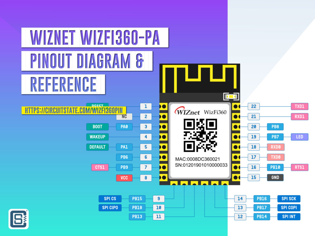
Complete pinout diagram and pin reference for the WizFi360-PA precertified Wi-Fi module from WIZnet.
WizFi360-PA is a precertified Wi-Fi module based on the W600 wireless SoC. The module is produced by WIZnet, a South Korean company expertising in network and connectivity solutions. W600 is a single-core ARM Cortex M3 microcontroller that integrates a Wi-Fi radio and other peripherals. The CPU can run at a maximum clock of 80MHz. It has an SRAM of 288 KB and a flash memory of 1 MB. The chip has a rich set of peripherals and cryptographic accelerators. The nominal working voltage is 3.3V and the QFN-32 measures just 5 x 5mm. It is a close competitor to the ESP8266EX and ESP8285 from Espressif. The main difference between them is that the ESP8266 can run at double the clock speed of W600.
If you want to use the WizFi360-PA Wi-Fi module in your project or product, we have a getting-started tutorial on our website. We used the WizFi360-EVB-Pico board from WIZnet for the demonstration.
Getting Started with WizFi360-EVB-Pico – RP2040 and Wi-Fi Development Board from WIZnet
Specifications
WizFi360-PA
- WiFi 2.4G, 802.11 b/g/n
- Supports Station / SoftAP / SoftAP+Station operation modes
- Supports “Data pass-through” and “AT command data transfer” mode
- Supports serial AT command configuration
- Supports TCP Server / TCP Client / UDP operating mode
- Supports configuration of operating channel 1 ~ 13
- Supports auto 20MHz / 40MHz bandwidth
- Supports WPA_PSK / WPA2_PSK encryption
- Serial port baud rate up from 600bps to 2Mbps with 16 common values
- Supports up to 5 TCP / UDP links
- Obtaining IP address automatically from the DHCP server (Station mode)
- DHCP service for Wireless LAN clients (AP mode)
- Supports DNS for communication with servers by domain name
- Supports “Keep-Alive” to monitor TCP connection
- Supports “Ping” for monitoring network status
- Built-in SNTP client for receiving the network time
- Supports built-in unique MAC address and user configurable
- Supports firmware upgrade by UART Download / OTA (via WLAN)
- Industrial grade (operating temperature range: -40 ° C ~ 85 ° C)
- KC, CE, FCC, TELEC certification
W600
- Hardware
- 32-bit ARM Cortex-M3 CPU, operating frequency 80MHz
- Integrated 288KB RAM
- Integrated 1MB Flash
- 8 channel DMA controller
- Integrated 2.4GHz RF transceiver, supports IEEE 802.11 protocol.
- Integrated PA/LNA/TR-Switch
- Integrated 32.768 KHz oscillator
- Integrated LDO, power supply control and power-on-reset.
- Cryptographic hardware accelerators for PRNG, SHA1, MD5, RC4, DES, 3DES, AES and CRC.
- Interface
- SDIO 2.0 Device controller, supports SDIO 1-/4-bit and SPI operating mode. Operating frequency 0~50MHz.
- 2 x UART interface, supports RTS/CTS, baud rate: 1200bps~2Mbps.
- 1 x High speed SPI controller (0~50MHz)
- 1 x I2C (100/400 KHz)
- 5 channel PWM (2 channel PWM capture) with maximum frequency of 20MHz.
- 1 x I2S (full-duplex, 32-192KHz)
- 1 x ISO/IEC 7816
- Network and Protocol
- Supports GB15629.11-2006, IEEE802.11 b/g/n/e/i/d/k/r/s/w
- Supports WAPI2.0
- Supports Wi-Fi WMM/WMM-PS/WPA/WPA2/WPS
- Support for Wi-Fi Direct
- Supports EDCA channel access mode
- 20/40M bandwidth
- Supports STBC, GreenField, Short-GI, support reverse transmission
- Supports RIFS frame interval
- AMPDU, AMSDU
- Supports IEEE802.11n MCS 0~7, MCS32, transmission rate is up to 150Mbps
- Support for Short Preamble at 2/5.5/11Mbps rate delivery
- Supports HT-immediate Compressed Block Ack, Normal Ack, No Ack response mode
- Supports CTS to self
- AP support functions
- Supports simultaneous AP and STA modes
- In a BSS network, multiple multicast networks are supported, and each multicast network is supported in different encryption modes. The maximum number of multicast networks and the STAs that are connected to the network can be up to 32.
- When BSS network support is used as an AP, the total number of supported sites and groups is 32, and 16 sites are supported in the IBSS network
- Receive sensitivity:
- 20MHz MCS7 @ -71dBm
- 40MHz MCS7 @ -68dBm
- 54Mbps @ -73dBm
- 11Mbps @ -86dBm
- 1Mbps @ -95dBm
- Allowable carrier frequency deviation: 50ppm
- Allowable sampling frequency deviation: 50ppm
- Support different encryption modes STA communication
- Support a variety of different receive frame filtering options
- Support for monitoring
- Power Supply
- 3.3V power supply
- Support PS-Poll, U-APSD low power management
- Standby power consumption is less than 10uA
- Packaging
- QFN32, 5mm x 5mm package
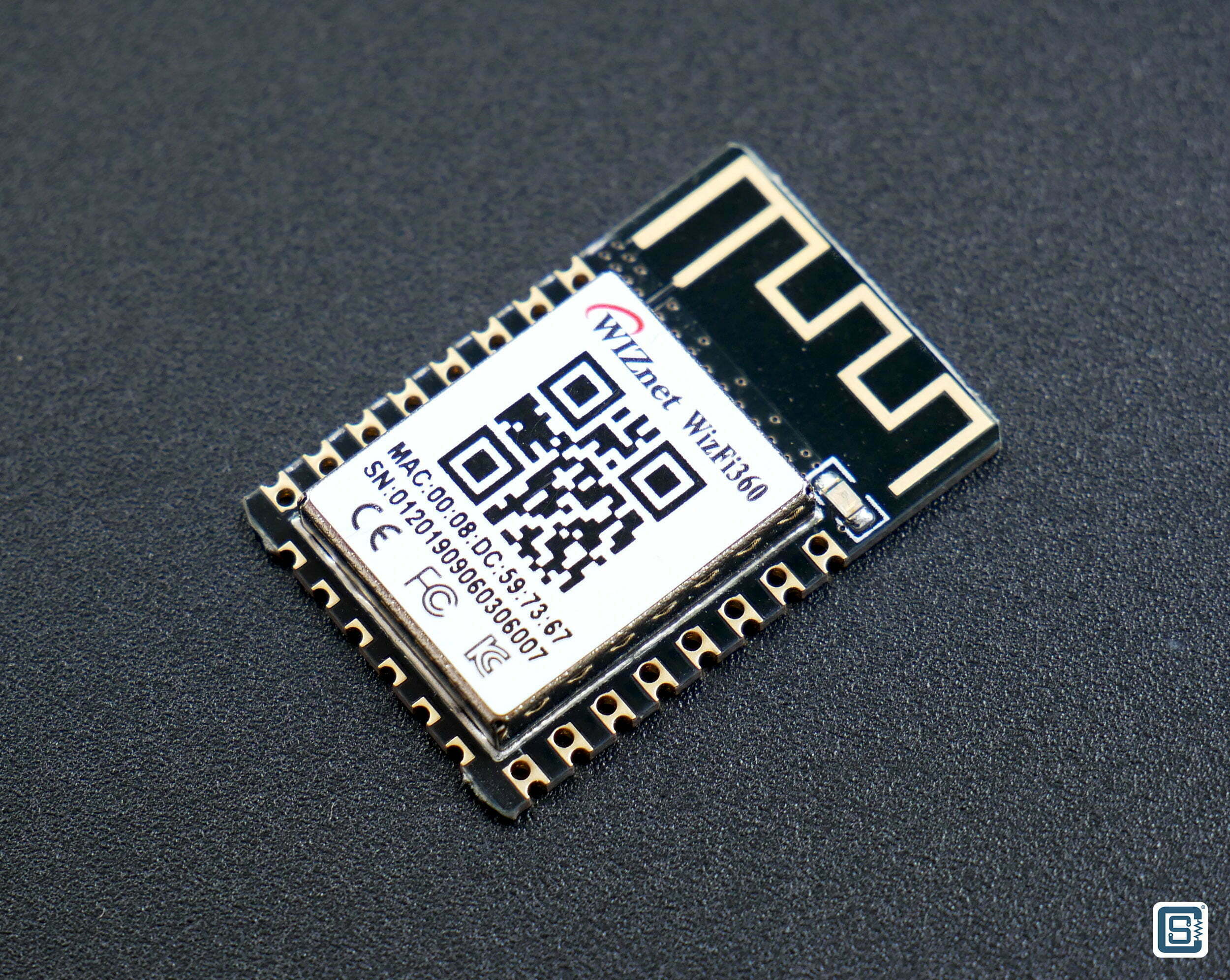
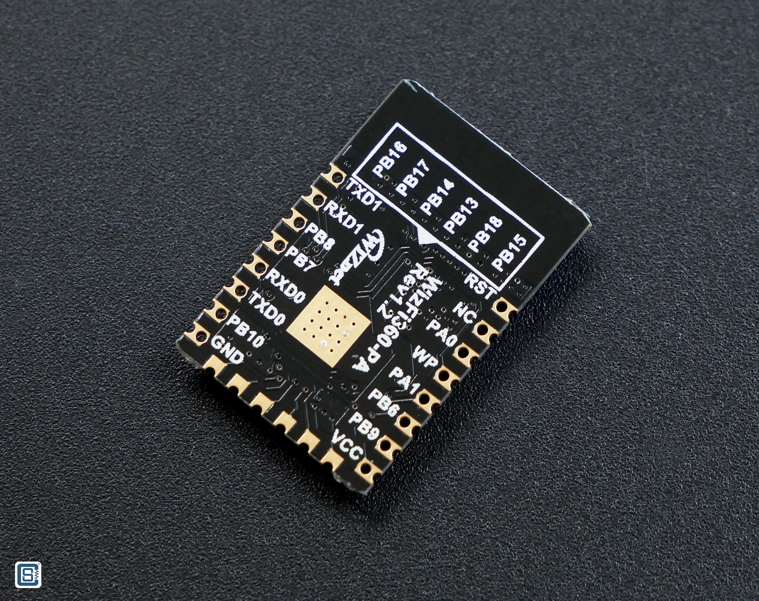
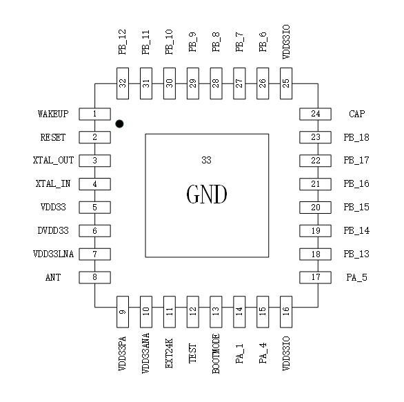
Pinout Diagram
Latest Revision: Rev 0.2, 06-12-2022
Design by: Vishnu Mohanan
License: CC-BY-SA 4.0
Pinouts are based on the latest documentation from the manufacturer. While we try our best to be accurate and up-to-date here, we can not guarantee correctness. Please also double-check the pin assignments with that from the official documentation. If you find any errors here, please let us know in the comments. We will update our designs ASAP.
PNG
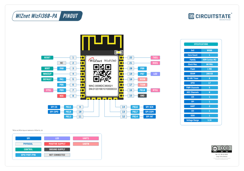
PDF preview may not load on mobile devices. Click the link to open an interactive preview, or download it directly.
Pin Reference
| Pin No. | Pin Name | Type | Description |
|---|---|---|---|
| 1 | RST | Input | Module Reset Pin (Active Low) |
| 2 | NC | – | Reserved |
| 3 | PA0 | I/O | BOOT Pin (Active low) When power on or reset is low, it operates in Boot mode. In the normal operating mode, this pin can be controlled by AT command. |
| 4 | WP | Input | WAKE-UP Pin (Active High) If the wake-up pin is high in Standby mode, the WizFi360 is reset to the normal operating mode. |
| 5 | PA1 | Input | Pull down over 3s for taking effect. UART1’s current parameter changes to the default value (please refer to the AT+UART_CUR command in WizFi360 AT command manual). |
| 6 | PB6 | I/O | This pin can be controlled by AT command. |
| 7 | PB9 | Input | CTS Pin of UART1 If you don’t use the CTS function, this pin can be controlled by AT command. |
| 8 | VCC | Power | Power Pin (Typical Value 3.3V) |
| 9 | PB15 | I/O | CSn Pin of SPI If you don’t use the SPI function, this pin can be controlled by AT command. |
| 10 | PB18 | I/O | MISO Pin of SPI If you don’t use the SPI function, this pin can be controlled by AT command. |
| 11 | PB13/SPI_EN | I/O | Enable Pin of SPI When power is applied or reset, this pin is checked to set the module mode. High or NC – UART Mode (Default) Low – SPI Mode |
| 12 | PB14 | I/O | INTn Pin of SPI If you don’t use the SPI function, this pin can be controlled by AT command. |
| 13 | PB17 | I/O | MOSI Pin of SPI If you don’t use the SPI function, this pin can be controlled by AT command. |
| 14 | PB16 | I/O | CLK Pin of SPI If you don’t use the SPI function, this pin can be controlled by AT command. |
| 15 | GND | Power | Ground Pin |
| 16 | PB10 | Output | RTS Pin of UART1 If you don’t use the RTS function, this pin can be controlled by AT command. |
| 17 | TXD0 | Output | TXD Pin of UART0 (AT command port) |
| 18 | RXD0 | Input | RXD Pin of UART0 (AT command port) |
| 19 | PB7 | Output | LED Light output (Active High). Go to High while each TX/RX packet and then back to Low. Note: It has been connected to the onboard LED for WizFi360-PA |
| 20 | PB8 | I/O | This pin can be controlled by AT command. |
| 21 | RXD1 | Input | RXD Pin of UART1 (Debug port) |
| 22 | TXD1 | Output | TXD Pin of UART1 (Debug port) |
Links
- Winnermicro W600 – Product Page
- W600 Datasheet – PDF
- WizFi360 Datasheet – PDF
- WizFi360 AT Instruction Set – PDF
- WizFi360 Hardware Design Guide – PDF
- WizFi360-EVB-Pico – Official Wiki Page
- WizFi360-EVB-Pico – Hardware Design Files
- WIZnet India Website and Store
- Official WizFi360 Library for Arduino
- WizFi360-EVB-Pico-C – C/C++ Examples
- Hercules Setup Utility
Short Link
- Short URL to this page – https://www.circuitstate.com/wizfi360pin

