Espressif ESP-Prog ESP32 JTAG Debug Probe – Pinout Diagram
Vector pinout diagram and pin reference for official ESP-Prog JTAG debug probe and programmer for ESP32 SoC from Espressif.
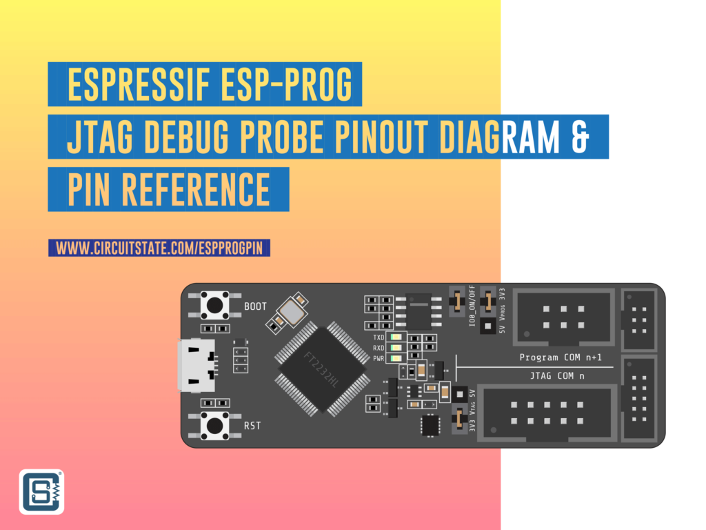
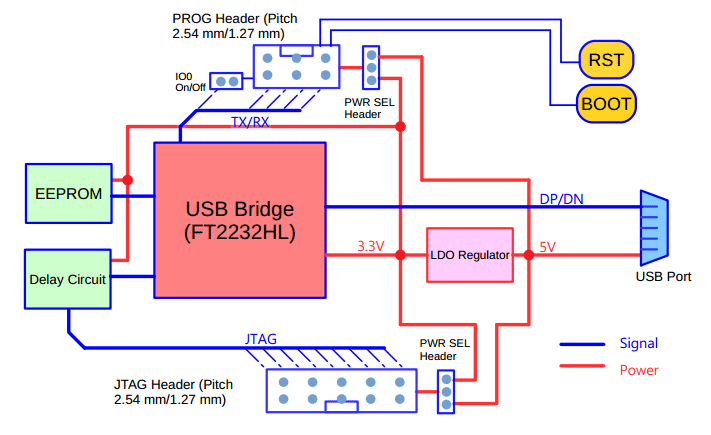
ESP-Prog is the official debug probe (debugger and programmer) for the ESP32 SoC family from Espressif. It integrates the FT2232HL USB to dual-channel UART/FIFO/JTAG/SPI/I2C converter from FTDI. ESP-Prog can be used to upload firmware to ESP32 boards using JTAG or Serial port, and to debug ESP32 Arduino and ESP-IDF projects through JTAG. On this page, you will find a vector pinout diagram for the ESP-Prog.
Block Diagram
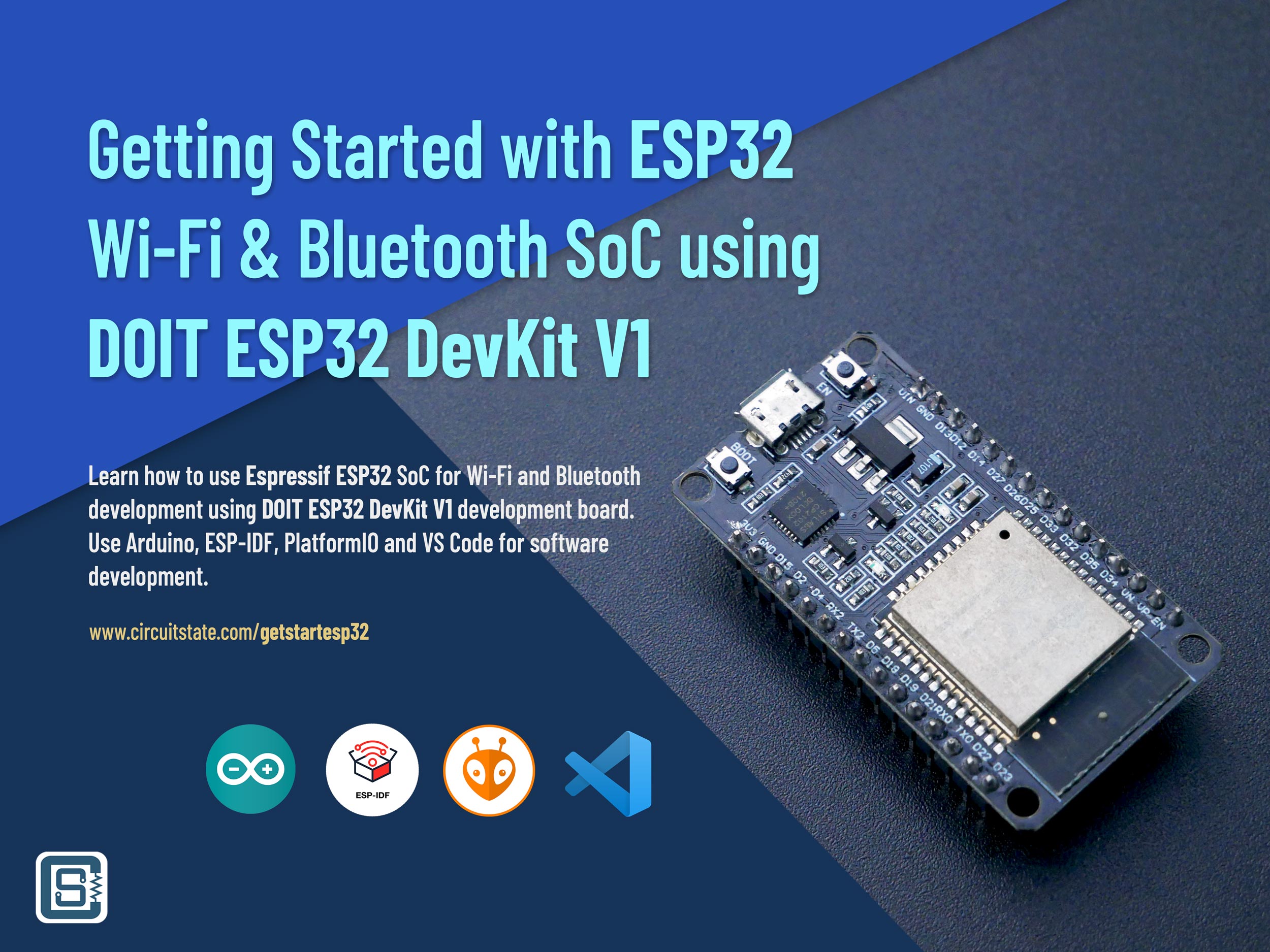
If you are new to ESP32 Wi-Fi and Bluetooth SoC, we have a dedicated tutorial to get you started.
Getting Started with Espressif ESP32 Wi-Fi & Bluetooth SoC using DOIT-ESP32-DevKit-V1 Development Board
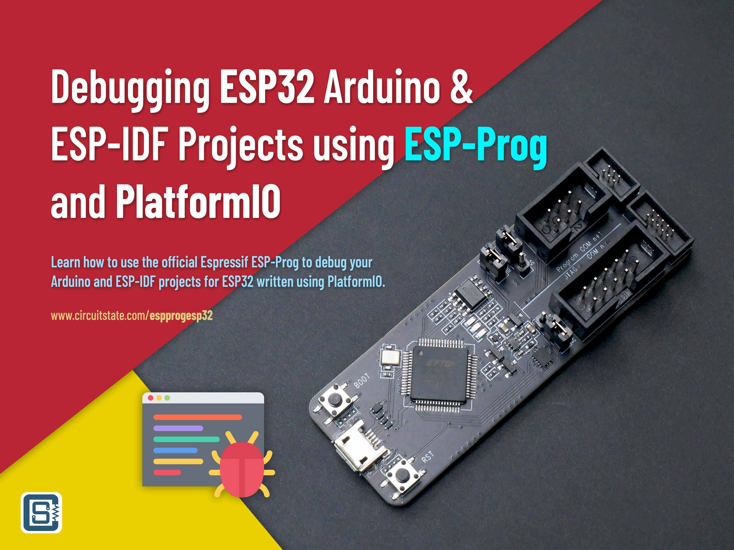
If you want to learn how to use the ESP-Prog to debug your ESP32 Arduino and ESP-IDF projects using DOIT ESP32-DevKit-V1 and PlatformIO, please check out the following tutorial.
Debugging ESP32 Arduino & ESP-IDF Projects using ESP-Prog and PlatformIO
Schematic
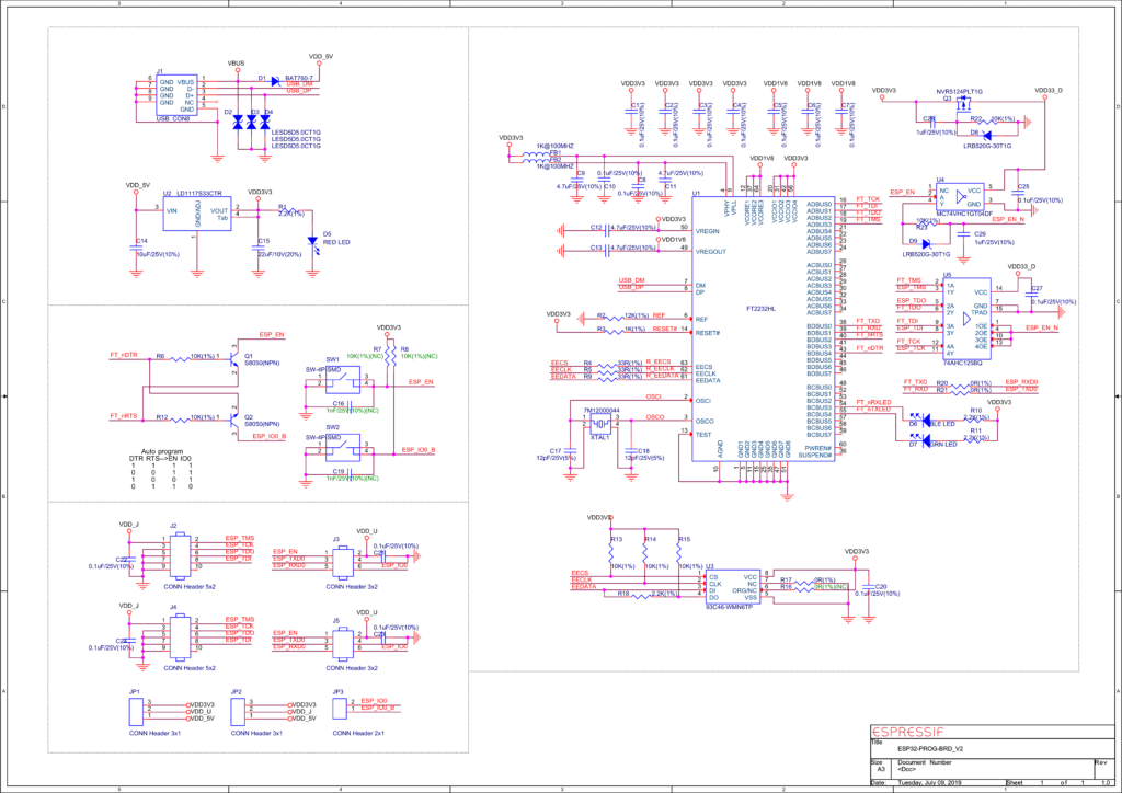
ESP-Prog supports both 5V and 3.3V supplies for the target. Two 3-pin jumpers are provided to select the target voltage. ESP32 SoCs require 3.3V and therefore you must not put the jumpers to 5V mode. You can also disconnect ESP-Prog from the GPIO0 (Boot pin) using the IO0_ON/OFF jumper.
Pinout Diagram
Latest Revision: Rev 0.1, 06-12-2022
Design by: Vishnu Mohanan
License: CC-BY-SA 4.0
Pinouts are based on the latest documentation from the manufacturer. While we try our best to be accurate and up-to-date here, we can not guarantee correctness. Please also double-check the pin assignments with that from the official documentation. If you find any errors here, please let us know in the comments. We will update our designs ASAP.
PNG
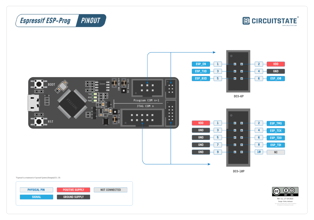
ESP-Prog has both 2.54 mm and 1.27 mm headers (IDC sockets) with identical pinouts for connecting to your board. The package comes with 6-pin and 10-pin 1.27 mm ribbon cables.
PDF preview may not load on mobile devices. Click the link to open an interactive preview, or download it directly.
Pin Reference
| Pin No. | Pin Name | Description |
|---|---|---|
| 1 | ESP_EN | Connects to the RST pin of the target ESP32. |
| 2 | VDD | Supply voltage from ESP-Prog. Can be 3.3V or 5V. |
| 3 | ESP_TXD | Connects to TXD0 pin of ESP32. |
| 4 | GND | Ground/Negative supply pin. |
| 5 | ESP_RXD | Connects to RXD0 pion of ESP32. |
| 6 | ESP_IO0 | Connects to GPIO0 (Boot) pin of ESP32. |
| Pin No. | Pin Name | Description |
|---|---|---|
| 1 | VDD | JTAG supply voltage from ESP-Prog. Can be 3.3V or 5V. |
| 2 | ESP_TMS | JTAG TMS |
| 3, 5, 7, 9 | GND | Ground/Negative supply. |
| 4 | ESP_TCK | JTAG TCK |
| 6 | ESP_TDO | JTAG TDO |
| 8 | ESP_TDI | JTAG TDI |
| 10 | NC | Not connected |
Links
- Getting Started with Espressif ESP32 Wi-Fi & Bluetooth SoC using DOIT-ESP32-DevKit-V1 Development Board
- Debugging ESP32 Arduino & ESP-IDF Projects using ESP-Prog and PlatformIO
- DOIT ESP32 DevKit V1 Wi-Fi Development Board – Pinout Diagram & Arduino Reference
- ESP-Prog Official Documentation
- ESP-Prog Schematic [PDF]
- FTDI FT2232HL – Product Page
- FTDI VCP Drivers
- Zadig USB Driver Installer
- ESP32 JTAG Debugging Documentation
Short Link
- Short URL to this page – https://www.circuitstate.com/espprogpin
