16×2 Character LCD Pinout Diagram & Pin Reference
Complete pinout diagram and pin reference for all HD44780-based character LCD modules including 16x2, 20x4 and 128x64.

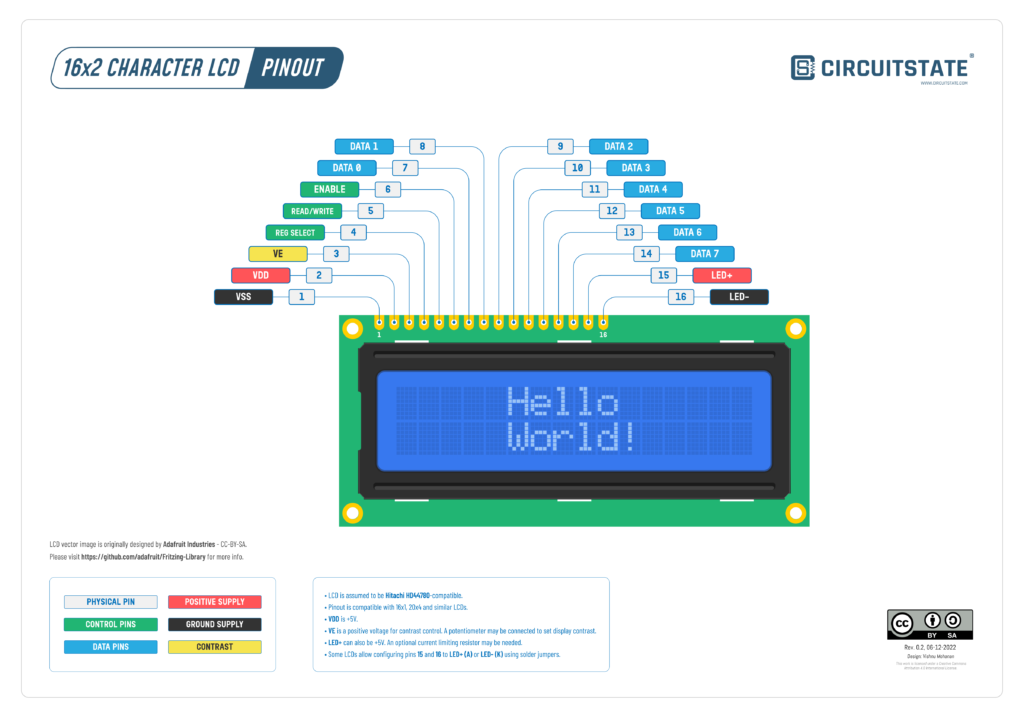
Character LCD is a simple and economical method for adding a display element to your electronic projects and products. You can see them being used in many consumer, industrial, and scientific devices. They are a great alternative to the old-school seven-segment displays. Character LCDs can show characters, icons, animations, and more. Their biggest limitations are the refresh rate, viewing angles, and relatively large sizes. Character LCDs come in different sizes, usually referred to by their horizontal and vertical character counts, such as 16×2, 20×4, etc. Most character LCDs you find today are based on or compatible with the Hitachi HD44780 LCD controller. In this post, you will find a high-quality vector pinout diagram for all HD44780-based LCD modules. Even though the title says 16×2, the pinout is compatible with other 20×2, 20×4, 24×2, and 128×64 LCDs as well.
Pinout Diagram
Latest Revision: Rev 0.2, 06-12-2022
Design by: Vishnu Mohanan
License: CC-BY-SA 4.0
Pinouts are based on the latest documentation from the manufacturer. While we try our best to be accurate and up-to-date here, we can not guarantee correctness. Please also double-check the pin assignments with that from the official documentation. If you find any errors here, please let us know in the comments. We will update our designs ASAP.
The vector image of the 16×2 LCD used in the pinout diagram was originally designed by Adafruit Industries, USA, and released under CC-BY-SA. Please check out the Adafruit website for info on their work and products.
PNG

PDF preview may not load on mobile devices. Click the link to open an interactive preview, or download it directly.
Pin Reference
| Pin # | Name | Type | Description |
|---|---|---|---|
| 1 | VSS | Power | Ground or negative supply |
| 2 | VDD | Power | Positive supply for the LCD. Should be 5V and less than 5V won’t work in most cases. |
| 3 | VE | Power | Positive supply voltage for contrast control. Contrast can be controlled with the help of a potentiometer or a voltage divider. |
| 4 | RS / REG SELECT | I | Register select pin. 0 = Instruction register for write. 1 = Data register for read and write. |
| 5 | R/W | I | Read/Write select pin. 0 = Write, 1 = Read |
| 6 | EN / ENABLE | I | Starts data read/write. |
| 7 | D0 / DATA0 | I/O | Data Pin 0 |
| 8 | D1 / DATA0 | I/O | Data Pin 1 |
| 9 | D2 / DATA0 | I/O | Data Pin 2 |
| 10 | D3 / DATA0 | I/O | Data Pin 3 |
| 11 | D4 / DATA0 | I/O | Data Pin 4 (4-bit mode) |
| 12 | D5 / DATA0 | I/O | Data Pin 5 (4-bit mode) |
| 13 | D6 / DATA0 | I/O | Data Pin 6 (4-bit mode) |
| 14 | D7 / DATA0 | I/O | Data Pin 7 (4-bit mode) |
| 15 | LED+ | Power | Backlight LED positive supply voltage. |
| 16 | LED- | Power | Backlight LED negative supply voltage. |
- LCD is assumed to be Hitachi HD44780-compatible.
- LCD uses 8-bit parallel data bus for communication.
- Supports both 4-bit and 8-bit modes. In 4-bit mode, only the higher-order data pins (D4-D7) have to be used.
- Pinout is compatible with 16×1, 20×4, and similar LCDs.
- VDD supply voltage is +5V.
- VE is a positive voltage for contrast control. A potentiometer may be connected to set display contrast.
- LED+ can also be +5V. An optional current-limiting resistor may be needed.
- Some LCDs allow configuring pins 15 and 16 selectively to LED+ (A) or LED- (K) using solder jumpers.
Links
- Hitachi HD44780 LCD Controller – Wikipedia
- Hitachi HD44780 – Datasheet [PDF]
- Standard LCD 16×2 + extras – white on blue – Adafruit
Short Link
- Short URL to this page – https://www.circuitstate.com/charlcdpin

