Interfacing TTE OCB350L250Z Non-Contact Tube Liquid Detection Sensor with Arduino
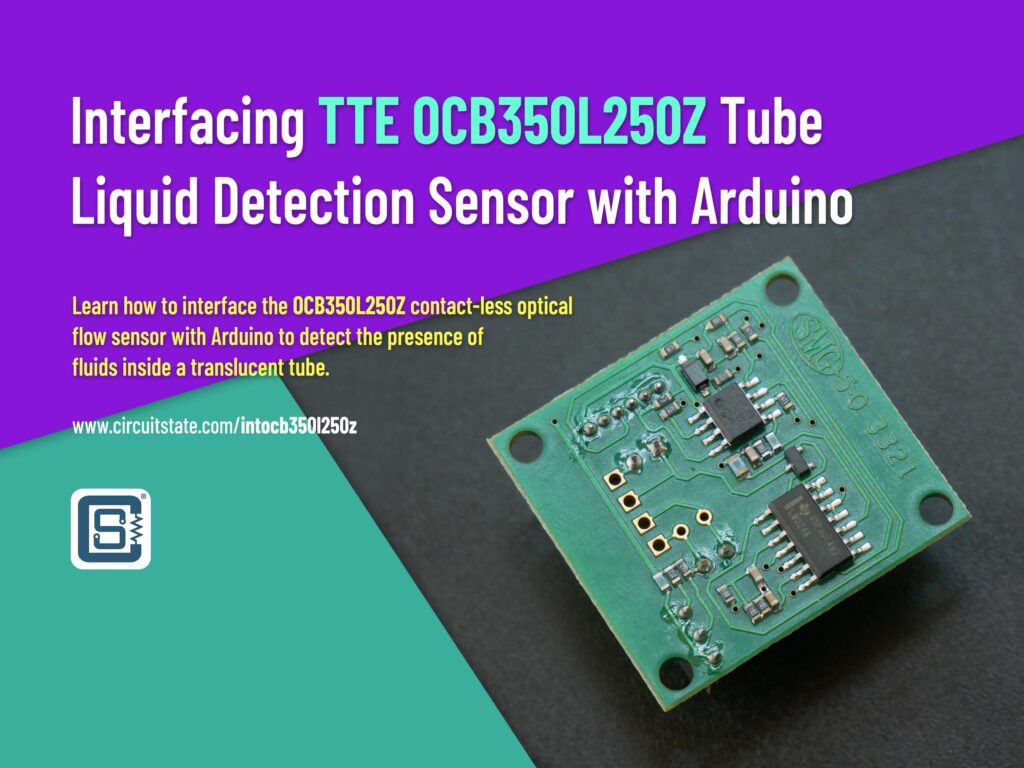
Learn how to interface the OCB350L250Z contact-less optical flow sensor with Arduino to detect the presence of fluids inside a translucent tube.
Detecting the presence of a liquid inside a tube can useful certain type of projects. There are multiple methods to detect the presence as well as the flow rate of liquids through tubes. Some of these techniques includes mechanical, electrical (resistive), optical and capacitive. In this short tutorial, we will see how an optical liquid detection sensor work and learn how to interface the OCB350L250Z evaluation board from TT Electronics/Optek Technology with Arduino.
OCB350L250Z
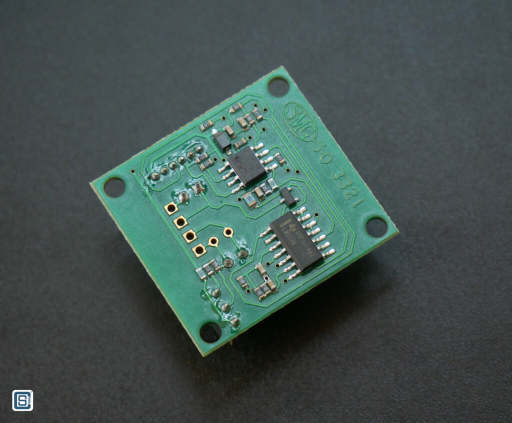
The OCB350L250Z is an evaluation board for the OCB350/OPB350 series tube liquid detection sensors from TT Electronics. The board contains the OCB350L250 sensor and the calibtration circuit (OCB100AZ). The board comes with a 6-pin OCB-100-MC24 cable.


Working Principle
The sensor works based on an LED and a Photodiode system and comes in different sizes and types. The working principle is the same for all sensors. The LED will emit a light of certain wavelength. The brightness of the light or the pulsing can be controlled by a host microcontroller. A photodiode will be placed some distance away from the LED facing towards it. Both the LED and the Photodiode are placed so that they face each other. This allows the maximum light from the LED to reach the Photodiode. The Photodiode will generate a voltage across its terminals when the light from the LED reaches it. The voltage produced is usually proportional to the intensity of the light from the LED.
Now if we place a transparent tube between the LED and the Photodiode and allow a liquid to pass through it, due to the presence of the liquid, the light will undergo multiple effects such as refraction and dispersion. This reduces the intensity of the LED light reaching the Photodiode. If we calibrate the system accurately, we can detect the difference between the voltage generated by the Photodiode when there is liquid inside the tube and when there is not. Doing this practically with just a normal LED and a Photodiode can be tricky, due to the calibration required. This is where products like OCB350/OPB350 can be useful. They are dedicated tube liquid detection sensors specifically made for the application. Both the LED and the Photodiode are chosen for the best performance for the liquid detection inside a tube. The sensor can detect the presence of a tube and any liquid inside the tube if properly calibrated. Such sensors are useful fluid dispensing applications such as IV fluids, oil, toner fluids etc.
Specifications
Following are the specifications of the OCB350L250 sensor.
| Property | Value |
|---|---|
| Sensor Type | Non-Contact, Optical |
| Wavelength | 935 nm |
| Photo Interrupter Type | Fluid |
| Mounting Type | Through-Hole |
| Tube Diameter | 1/4 Inch |
| Supply Voltage | 4.5 ~ 5.5V |
| Light Current (ON) | 1-3 mA |
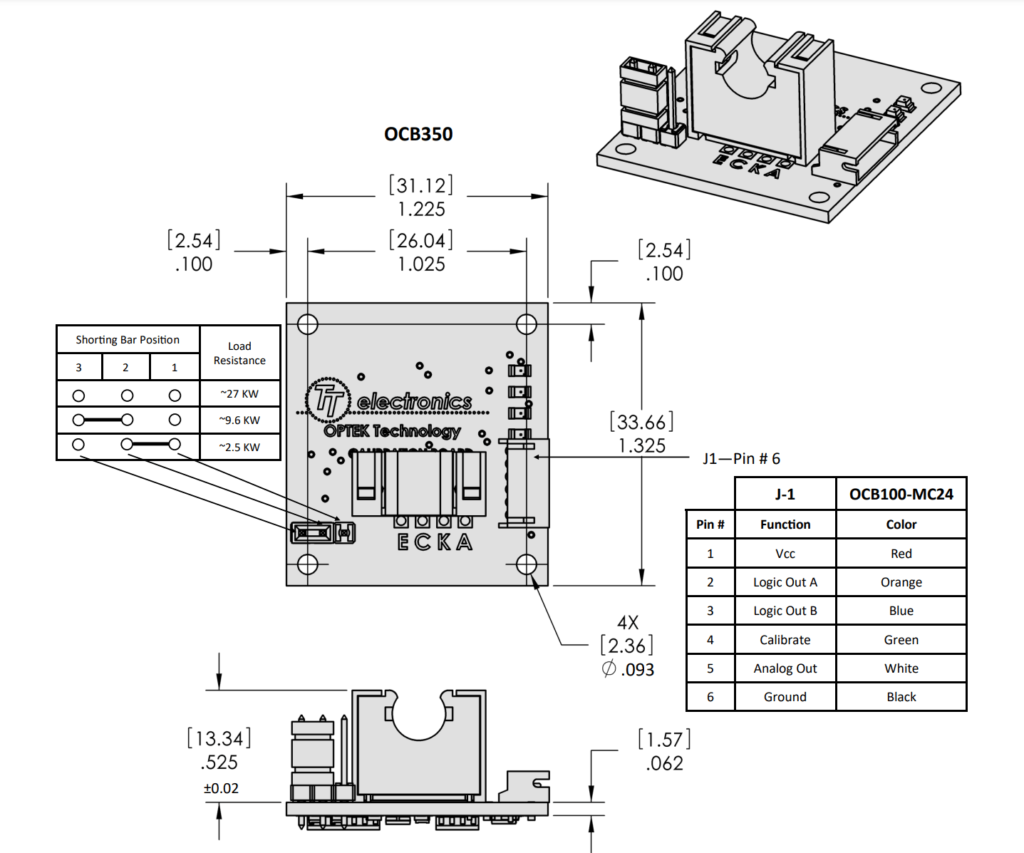
Pinout & Dimensions
Schematic
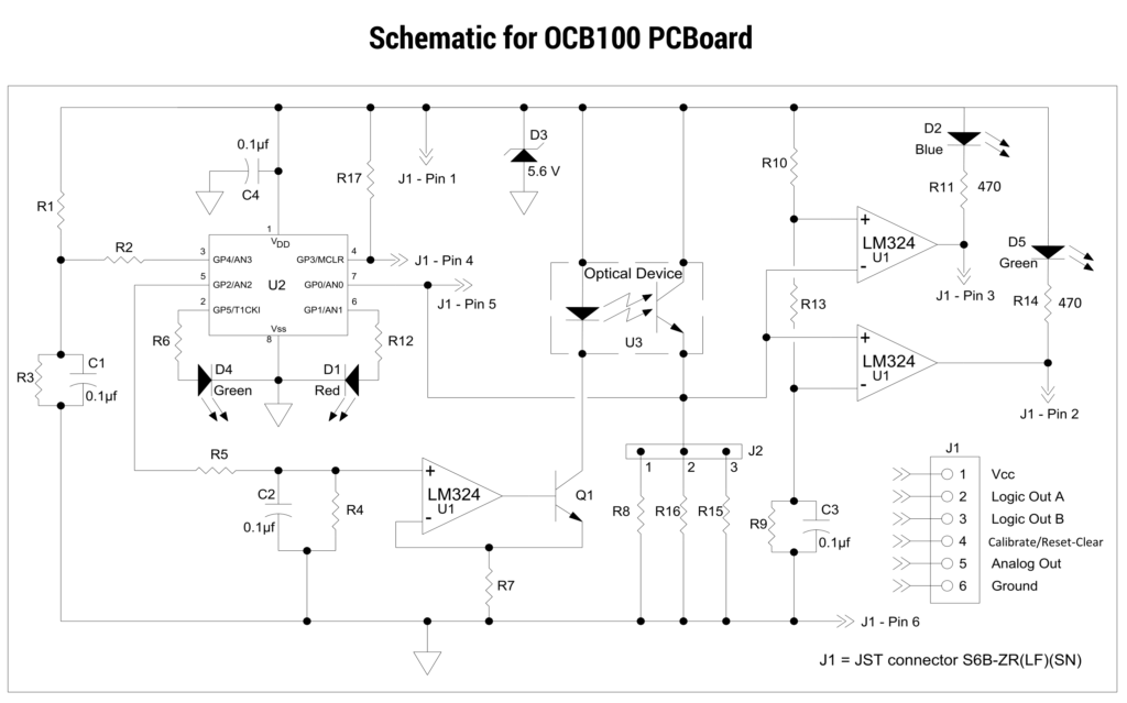
Following is the schematic of the OCB100 calibration board. U3 is the optical flow sensor.
Testing
There is a 6-pin JST connector for interfacing with a microcontroller. But even without a microcontroller, the board can indicate detection via the LEDs. There are four LEDs. A Blue LED will turn on when you connect the power without any tubes or obstacles between the sensor. If you block the sensor with any opaque material, the Blue LED will turn off and the Green LED will turn on.
When you place an empty Silicone tube in the sensor, all LEDs will turn off. As soon as any liquid reaches the sensor area, in this case, clean water, the Blue LED will again light up.
Arduino Code
We used the following Arduino code to test the sensor board.
int pin_logic_A = SDA;
int pin_logic_B = SCL;
int pin_analog = A4;

void setup() {
  Serial.begin (115200);
  pinMode (pin_logic_A, INPUT);
  pinMode (pin_logic_B, INPUT);
  pinMode (LED_BUILTIN, OUTPUT);
}

void loop() {
  Serial.print ("A: ");
  Serial.print (digitalRead (pin_logic_A));
  Serial.print (", ");
  Serial.print (" B: ");
  Serial.print (digitalRead (pin_logic_B));
  Serial.print (", ");
  Serial.print (" Analog: ");
  Serial.println (analogRead (pin_analog));

  delay (500);
}

The sensor uses the two logic output pins A and B to indicate four states.
| State | A | B | LED |
|---|---|---|---|
| Completely Unblocked (no tube) | 1 | 0 | Blue |
| Completely Blocked | 0 | 1 | Green |
| Tube Present | 1 | 1 | None |
| Tube + Water | 1 | 0 | Blue |
For some reason, we were not able to get the analog voltage from the sensor. It always returned 4095. The calibration pin (Green wire) can be used to calibrate the sensor. But this is only possible with the evaluation board because it has an 8-pin PIC microcontroller with the required firmware for a calibrated system. The manufacturer has not provided the firmware for it. So anybody who wants to use the sensor with a calibration feature has to either make their own calibration system or use the supplied board. There are three resistors with jumpers to set the sensitivity of the sensor.
Links
Short Link
- Short URL to this page – https://www.circuitstate.com/intocb350l250z
